


500
Solar-Log™ Smart Relay Box
Note!
The Solar-Log™ Smart Relay Box cannot be connected together with inverters on an RS485
interface. The Relay Box requires its own separate RS485 bus.
It is possible to combine the Utility Meter with sensors.
Note!
The Solar-Log™ Smart Relay Box cannot be connected together with PM+ packages on a So-
lar-Log™.
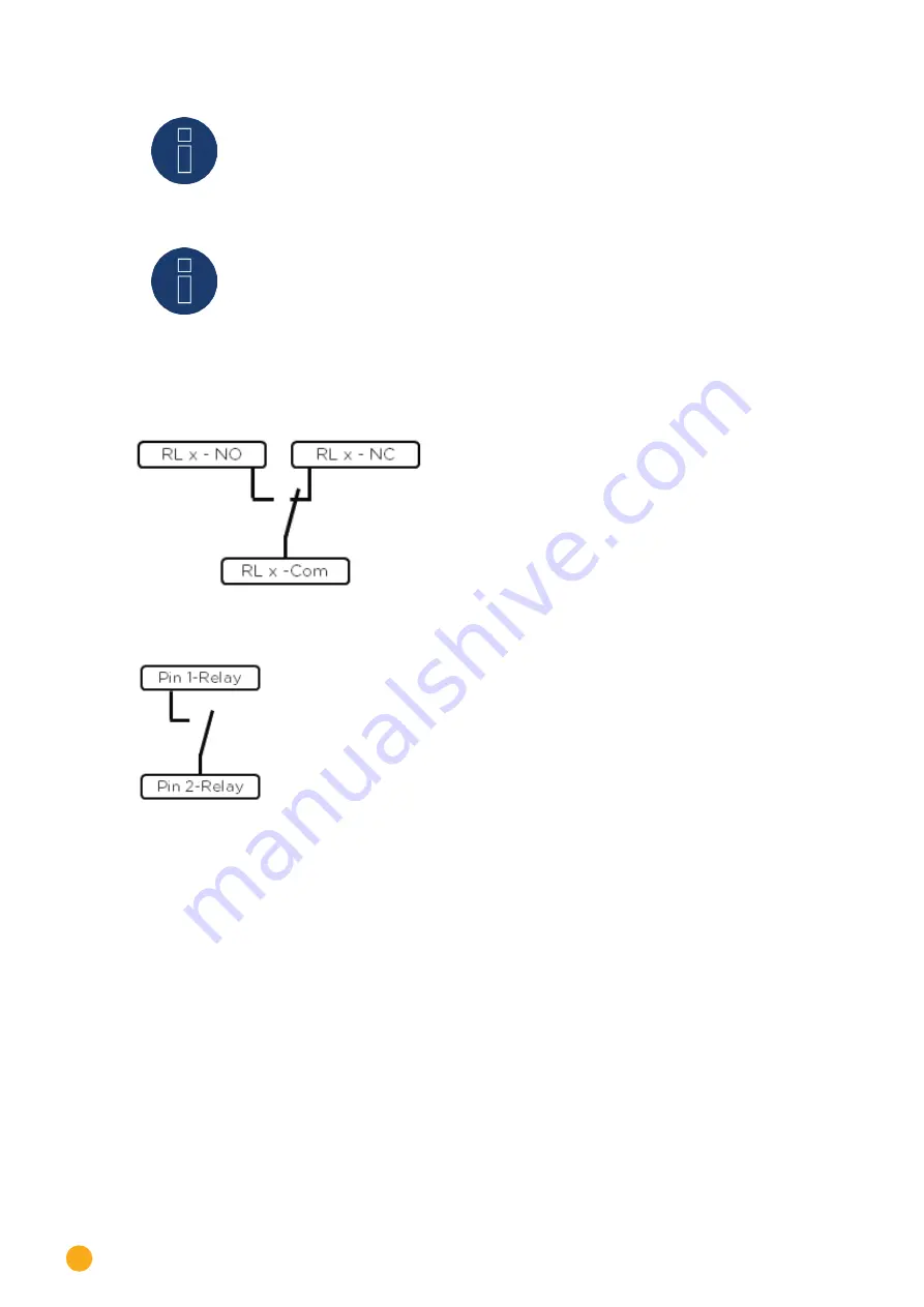
Relay output assignments
Fig.: Smart Relay Box relay output (change-over contact) diagram
Fig.: Smart Relay Box relay output (make contact) diagram
Содержание Solar-Log
Страница 1: ...1 Components Connection Manual V 4 2 3 Solar Log EN ...
Страница 20: ...20 01 Inverter ...
Страница 366: ...366 Surpass SSE Note Feed in management Power reductions of less than 10 are set by the inverters to 10 ...
Страница 398: ...398 Appendix 113Appendix 113 1 SMA mixed wiring Fig SMA mixed wiring ...
Страница 402: ...402 02 Meter ...
Страница 444: ...444 03 Battery Systems ...
Страница 456: ...456 sonnen Note Only one battery system can be connected to a Solar Log device ...
Страница 463: ...463 04 Heating rods ...
Страница 470: ...470 05 Heating pumps ...
Страница 478: ...478 06 Sensors ...
Страница 488: ...488 07 Pyranometer ...
Страница 495: ...495 08 Smart Plug components ...
Страница 502: ...502 09 Power Charging Stations ...