


114
EKO Energy
27 EKO Energy
27.1 EKO Energy
Termination
Addressing
Interface
Yes
Yes
RS485
Overview
•
Integrated interface.
•
Where to connect: Between the COM round sockets on the outside of the inverter.
•
2-pin wiring.
•
Communication address must be allocated.
•
Installation steps:
•
Switch off the inverters and Solar-Log™.
•
Connect inverters to the Solar-Log™.
•
Connect the inverters to each other.
•
Allocate communication address.
Connect inverters to the Solar-Log™
The wiring is done using a
•
ready-made data cable (supplied with the inverter).
or
•
self-made, shielded 2 wire data cable with round plug and terminal block connector.
Procedure
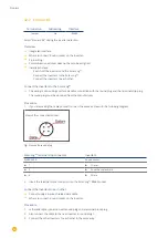
1. If you are making the cable yourself, connect the wires as shown in the following diagram:
Solar-Log™ terminal strip connector
Inverter round socket
Terminal
Terminal
►
1
►
1
►
4
►
2
2. Insert the round plug into any COM round socket on the inverter.
3. If no further inverter is connected, terminate the inverter according to the instructions for the inverter.
4. Insert the terminal block connector into the Solar-Log™ RS485 socket.
Connect the inverters to each other
•
Connect using a self-made daisy chain cable.
•
Where to connect: Between the COM round sockets on the outside of the inverter.
Содержание Solar-Log
Страница 1: ...1 Components Connection Manual V 4 2 3 Solar Log EN ...
Страница 20: ...20 01 Inverter ...
Страница 366: ...366 Surpass SSE Note Feed in management Power reductions of less than 10 are set by the inverters to 10 ...
Страница 398: ...398 Appendix 113Appendix 113 1 SMA mixed wiring Fig SMA mixed wiring ...
Страница 402: ...402 02 Meter ...
Страница 444: ...444 03 Battery Systems ...
Страница 456: ...456 sonnen Note Only one battery system can be connected to a Solar Log device ...
Страница 463: ...463 04 Heating rods ...
Страница 470: ...470 05 Heating pumps ...
Страница 478: ...478 06 Sensors ...
Страница 488: ...488 07 Pyranometer ...
Страница 495: ...495 08 Smart Plug components ...
Страница 502: ...502 09 Power Charging Stations ...