481
Sensor Basic
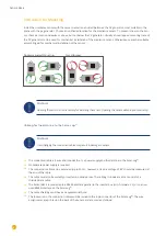
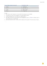
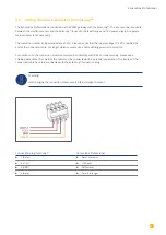
Terminal block connector Solar-Log™
Sensor Basic Cable
►
1 (Data+)
►
Brown Data+
►
2 (+12V)
►
Red +12Vdc (Vcc)
►
3 (GND)
►
Black 0 V (GND)
►
4 (Data-)
►
Orange Data-
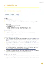
Startup
1. When the Solar-Log™ is switched on, the Sensor Basic is also powered up automatically
2. The Sensor Basic must then be configured on the desired RS485 interface:
3. Use the web interface to access the Solar-Log™ configuration menu.
4. Select “M&T Sensor” for the inverter selection in the
Configuration | Devices | Definition | Interfaces
menu in
the sector
Device class | Manufacturer
.
5. Carry out the inverter detection. The Sensor Basic is integrated with the system in the same way as an inverter.
Содержание Solar-Log
Страница 1: ...1 Components Connection Manual V 4 2 3 Solar Log EN ...
Страница 20: ...20 01 Inverter ...
Страница 366: ...366 Surpass SSE Note Feed in management Power reductions of less than 10 are set by the inverters to 10 ...
Страница 398: ...398 Appendix 113Appendix 113 1 SMA mixed wiring Fig SMA mixed wiring ...
Страница 402: ...402 02 Meter ...
Страница 444: ...444 03 Battery Systems ...
Страница 456: ...456 sonnen Note Only one battery system can be connected to a Solar Log device ...
Страница 463: ...463 04 Heating rods ...
Страница 470: ...470 05 Heating pumps ...
Страница 478: ...478 06 Sensors ...
Страница 488: ...488 07 Pyranometer ...
Страница 495: ...495 08 Smart Plug components ...
Страница 502: ...502 09 Power Charging Stations ...


