


36
10601034 Rev. B
LENS Integrated System
Operations/Service Manual
Customize Procedure Settings
Zoom
See trace for detail [560: ZOOM - Increase or decrease from 1.0X to
2.5X. Each time the button is pressed, the zoom factor increases by
approximately 10%, going through the following discrete zoom factors:
1.0X, 1.2X, 1.3X, 1.5X, 1.7X, 1.9X, 2.1X, 2.3X, 2.5X.]
Configure Icons
The
CONFIGURE ICONS setting allows the user to customize which
icons appear in the status bar on the OSD. The default setting for all
icons is
YES.
To customize the icons display in the status bar:
1. Navigate to the procedure to be customized. and press
Select. The
CUSTOMIZE PROCEDURE screen opens.
2. Navigate to
CONFIGURE ICONS and press Select to select it. The
CONFIGURE ICONS screen opens (Figure 40). Each icon listed can
be configured to
YES (display) or NO (do not display).
Figure 40 .
3. Navigate to the desired icon. When the icon blinks, press
Select to
select it. The current setting will blink.
4. Use the
Up and Down arrows on the control unit or the left and right
camera head buttons to switch between
YES and NO. Press Select
to select the desired setting.
Icons displayed can be enabled or disabled individually or as a group.
To
ENABLE all icons in the status bar, navigate to ENABLE ALL. When
ENABLE ALL blinks, press Select to select it. All icons listed on the
screen will immediately be reconfigured to
YES and will appear in the
status bar on the OSD.
To
DISABLE all icons in the status bar, navigate to DISABLE ALL. When
DISABLE ALL blinks, press Select to select it. All icons listed on the
screen will immediately be reconfigured to
NO and will not appear in
the status bar. This is not recommended.
To exit the CONFIGURE ICONS screen, highlight the
EXIT option and
press
Select to return to the CUSTOMIZE PROCEDURE SETTINGS
screen.
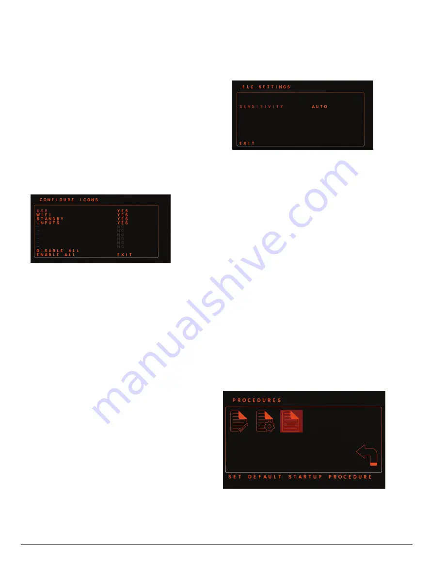
ELC Settings
ELC (Electric Light Control) Settings allows the user to customize the
response of the ELC. The recommended setting is
AUTO, which is also
the default setting.
It can also be set to sensitivity levels 1–16.
If flicker occurs while the ELC is set to
AUTO, reset the ELC to 1 to
remove the flicker, then increase the sensitivity level until the speed of
the ELC response is sufficient. When sensitivity is set to 1, the response
time of the ELC is slow, but more stable. At 16, the response time is
quick, but less stable.
To customize
ELC Settings:
1. Navigate to
ELC Settings and press Select to select it. The ELC
Settings screen (Figure 41) opens.
Figure 41 .
2. Press
Select to select SENSITIVITY. The current setting will blink.
3. Use the
Up and Down arrows on the control unit or the left and right
camera head buttons to scroll through the settings options. Press
Select to select the desired sensitivity level or AUTO.
To exit the ELC SETTINGS screen, highlight the
EXIT option and press
Select to return to the CUSTOMIZE PROCEDURE SETTINGS screen.
Save and Exit
To save all changes to the procedure, navigate to
SAVE AND EXIT.
Press
Select to save changes and exit to OSD. To exit without saving
changes, custom settings will need to be changed manually to their
original settings prior to selecting
SAVE AND EXIT .
Set the Default Startup Procedure
Set Default Startup Procedure allows the user to set the procedure
that is highlighted on the STARTUP screen and so can be selected
immediately. To set the default startup procedure:
1. Navigate to the
Procedures icon and press the Select button to
select it.
2. Highlight the
Set Default Startup Procedure icon (Figure 42) and
press the
Select button to select it. A screen showing the available
procedures opens.
3. Use the
Up and Down arrows on the control unit or the left and
right camera head buttons to scroll to the procedure to be set as the
default procedure. Press
Select to select the procedure and return
to the OSD.
Figure 42 .
Содержание LENS Integrated System
Страница 1: ...LENS Integrated System Operations Service Manual...
Страница 2: ......
Страница 45: ......
Страница 46: ......
Страница 47: ......


