


21
10601034 Rev. B
LENS Integrated System
Operations/Service Manual
Inspect the System Components
The STARTUP menu remains on the screen until a procedure or the
Menu Access icon is selected.
Note: When a procedure is selected, the camera will automatically
perform a white balance. If a camera head is connected, ensure
that the camera head is pointed at a white object such a a piece of
gauze or a piece of paper. At this point, the camera is in Live Video
mode.
Note: Procedures stored on the App will not appear on the STARTUP
menu. However, the name of the procedure in use appears in the
patient information box on the OSD.
Note: If a camera head is not plugged in, or if the camera head
is unplugged while the control unit is on, the monitor will display
a color bar pattern. When the camera head is plugged back in,
perform a White Balance.
2. Press the
Illumination button on the front of the control unit to turn
on the light source. The button illuminates orange.
Connect the iPad
If the control unit in use has a Wi-Fi feature, the LENS iPad Application
(App) can now be connected to the system. Refer to the LENS iPad
Application Instructions for Use (REF 10601295) for information about
how to download the App and connect it to the LENS System.
Note: The Wi-Fi icon notifies the user the that the iPad is
communicating or not communicating with the control unit. If the Wi-Fi
connection between the App and the control unit is lost, the WiFi icon
on both the OSD status bar and the iPad will change from orange to
gray. The APP will automatically connect when the signal is available
again. Should the connection be lost or interrupted during surgery, all
control unit control features can be accessed either from the front panel
of the control unit or the camera head buttons.
Inspect the System Components
Prior to using the LENS Integrated System, it is essential that all system
components be inspected for damage which can negatively impact the
system’s performance. Inspection should include all equipment to be
used in surgery, including cables and peripheral devices.
CAUTION: Prior to each use, inspect the device to ensure it is functioning
properly and is not damaged. Do not use a damaged device.
Electrical Connections
Examine the electrical connections.
• Electrocautery and other electrical noise-inducing medical
equipment can interfere with the performance of control
units and monitors. To prevent interference, plug monitors
and camera equipment into an outlet on a wall separate from
noise-inducing equipment.
• Check that the electrical equipment is properly grounded
(i.e., plugs contain a ground prong). The control unit must be
plugged into a hospital-grade AC outlet.
• If the monitor has a termination switch, it needs to be set to
75U. If two or more monitors are used, only the termination
switch on the last monitor needs to be on. If there is no
termination switch on the last monitor; the monitor is
self-terminating.
Double-check the equipment setup diagrams to ensure that all
connections are correct.
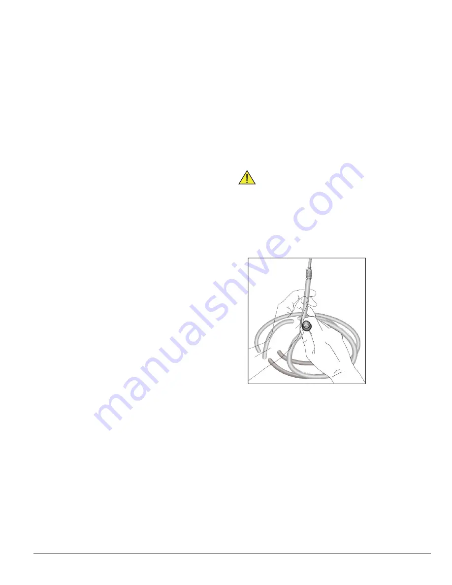
Inspect the Fiber Optic Light Cable
WARNING: When inspecting the light cable, NEVER aim the
light cable at the light source . Retinal damage may occur .
• Check the sheath for damage. Cuts, abrasions, or tears in the
cable’s silicone sheath will reduce overall light transmission.
• Aim one end of the cable toward a bright light, such as a room light,
and inspect the other end for damaged fibers, e.g., black dots or
dark gray areas (Figure 11). A combination of broken fibers in the
cable or endoscope will result in reduced light transmission. The
combined percentage of dark spots viewed in the cable end should
not exceed 20% of its total area.
Figure 11 . Inspect the fiber optic light cable
• Perform a visual fiber bundle diameter comparison. For optimal light
transmission, the diameter of the fiber bundles in the endoscope’s
fiber optic light post should match the fiber bundle diameter of the
light cable. This will prevent unnecessary heat buildup at the scope/
light guide connection.
Содержание LENS Integrated System
Страница 1: ...LENS Integrated System Operations Service Manual...
Страница 2: ......
Страница 45: ......
Страница 46: ......
Страница 47: ......


