Smith & Nephew LENS Integrated System Скачать руководство пользователя страница 30

30

10601034 Rev. B

LENS Integrated System     

Operations/Service Manual

Customize the System

Set/Change Admin Password 

The administrator password allows the site to prevent any changes to 

the system settings.
Note: A user will still be able to create a user password to allow 

controlled access to the CUSTOMIZE PROCEDURE SETTINGS menu.
To set or change the administrative password:
1.  Select the 

SET/CHANGE ADMIN PASSWORD icon to open the 

CHANGE PASSWORD screen.

2.  Select 

PASSWORD REQUIRED . The current setting (YES or NO) will 

blink. 

3.  Use the 

Up and Down arrows on the control unit or the left and right 

camera head buttons to switch between 

YES and NO.  

4.  Press 

Select to select either YES or NO. To save the setting, 

navigate to 

SAVE AND EXIT and press Select. To return to the 

System Configuration menu without saving any changes, select 

CANCEL

If 

Yes is selected, a blinking NEW PASSWORD = option appears on the 

screen (Figure 25). 

Figure 25 .  
5.  Press 

Select to select NEW PASSWORD =. An OSD keyboard 

appears below the CHANGE PASSWORD menu (Figure 26). 

Figure 26 .  

6.  Use the 

Up and Down arrows on the control unit or the left and 

right camera head buttons to navigate to the desired letters on the 

keyboard. 
Note: A short press moves the highlighted cursor left or right. A 

long press moves the cursor up or down from line to line. To select 

a letter, number, or symbol, press 

Select. To exit the keyboard, 

navigate to the 

Return key and press Select

7.  To save the changes and exit the CHANGE PASSWORD screen, 

select 

SAVE AND EXIT to return to the SYSTEM CONFIGURATION 

MENU screen. To exit the screen without saving any changes, 

navigate to 

CANCEL and press Select to return to the SYSTEM 

CONFIGURATION MENU screen.

Note: Do not lose the administrative password. This will prevent the 

recovery of passwords through the RESET FACTORY DEFAULTS function. 

If the administrator password is lost, please contact Smith & Nephew.

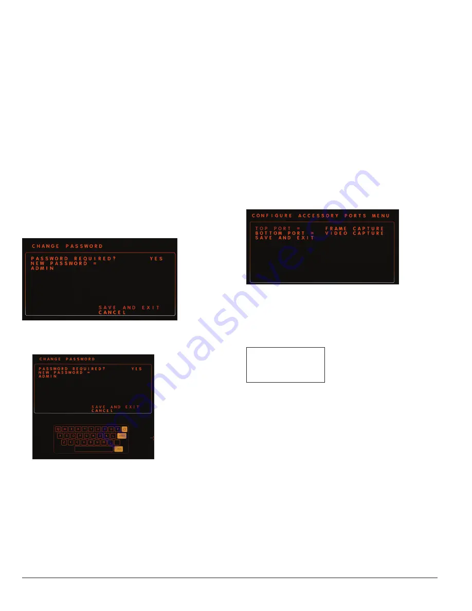
Configure Peripheral Ports

The CONFIGURE ACCESSORY PORTS MENU screen allows the user to 

configure the peripheral ports on the rear panel of the control unit to the 

desired function. To configure the peripheral ports: 
1.  Select the 

CONFIGURE ACCESSORY PORTS icon on the SYSTEM 

CONFIGURATION MENU screen to open the CONFIGURE 

ACCESSORY PORTS MENU screen (Figure 27). 

TOP PORT = will 

blink. The default setting is 

FRAME CAPTURE.

Figure 27 .  

2.  To customize the 

TOP PORT, press Select. The current setting to the 

right of 

TOP PORT will begin to blink. 

3.  Use the 

Up and Down arrows on the control unit or the left and right 

camera head buttons to scroll through the available options (Figure 

28). 

FRAME CAPTURE 

GENERAL PURPOSE 

VIDEO CAPTURE

Figure 28 .  

4.  Navigate to the desired setting and press 

Select


– Select 

FRAME CAPTURE to send a still frame to the digital image 

capture device.


– Select 

GENERAL PURPOSE to send a still frame to the printer. 


– Select 

VIDEO CAPTURE to send video recordings to the digital 

image capture device. When 

VIDEO CAPTURE is in use, the first 

button press starts the recording, and the second button press 

stops the recording.

5.  To customize the settings for


the 

BOTTOM PORT, navigate to 

BOTTOM PORT and press Select . Repeat Steps 2 and 3 to change 

the current settings for 

BOTTOM PORT

6.  To save changes and exit the screen, select 

SAVE AND EXIT. To exit 

the screen without saving any changes, return all settings to their 

original settings and select 

Save and Exit .  

Содержание LENS Integrated System

Страница 1: ...LENS Integrated System Operations Service Manual...

Страница 2: ......

Страница 3: ...general waste Caution See Instructions for Use Follow instructions for use CE Mark Select button Danger Non ionizing electromagnetic radiation Brightness Power plug e Environmentally friendly use per...

Страница 4: ...uide 20 Turn the Camera Control Unit On 20 Connect the iPad 21 Inspect the System Components 21 Electrical Connections 21 Inspect the Fiber Optic Light Cable 21 Safety and Service Life Checklist 22 Op...

Страница 5: ...ction with the LENS Integrated System Wi Fi version is indicated for capture of still and motion pictures patient file management and limited redundant control of the LENS Control Unit within articula...

Страница 6: ...ion Do not plug the camera cable connector into the control unit if wet Moisture on the card edge of the camera cable will damage the circuitry and void the warranty Ensure that the card edge is compl...

Страница 7: ...parately and the optional LENS App It is configured to be connected as a stand alone system on an endoscopic cart or tower The System can be used in conjunction with compatible high definition flat pa...

Страница 8: ...is designed to accept the Smith Nephew Wolf Light Guide end fittings 9 Camera Cable Connector receptacle Compatible Smith Nephew camera heads can be connected via the card edge connector Be sure the...

Страница 9: ...ow control of peripheral devices such as printers and image capture devices from the camera head 5 Fuse Holder The clip holds a dual fuse See the Technical Specifications section of this manual 6 AC M...

Страница 10: ...a customized procedure The two functions are activated by a short press 1 0 seconds and a long press 1 0 seconds These buttons can be customized based on the user s needs Refer to the Button Settings...

Страница 11: ...utton settings refer to the Button Settings section of this manual Function Effect BRIGHTNESS Control the luminance level of the video output ENHANCEMENT Enhance the sharpness of the displayed video Z...

Страница 12: ...ce are connected to the System a patient name b number of images and videos recorded c current procedure name Note When both an iPad and a USB are connected the iPad information will appear on the OSD...

Страница 13: ...be placed on a platform or cart shelf equipped with a screw mount follow these instructions to secure the control unit to the platform or shelf 1 Center the control unit on the shelf and ensure that...

Страница 14: ...and HD SDI connectors BNC SDI composite To connect push in and turn BNC HDSI To connect push in and turn Note BNC SDI and BNC HDSI connectors appear identical For the highest quality image be sure to...

Страница 15: ...ol unit s rear panel 3 To record still or video images from the camera connect the App to the LENS Wi Fi network or a insert a USB storage device in one of the USB ports on the control unit Refer to t...

Страница 16: ...16 10601034 Rev B LENS Integrated System Operations Service Manual Installation Figure 5 Recommended setup configuration Wi Fi enabled System...

Страница 17: ...nagement system is compatible only with 1080i output Refer to the Advanced Settings section of this manual for information about how to configure input and output settings 4 To record still images fro...

Страница 18: ...Sistema integrado Integreret system Integrert system Endoscopy Smith Nephew Inc 150 Minuteman Road Andover MA 01810 USA T 1 978 749 1000 F 1 978 749 1108 Customer Service 1 800 343 5717 HDSDI 2 HDSDI...

Страница 19: ...rimary left and secondary right inputs Color Explanation Orange Ready White Input is not ready Red Recording or busy For example in Figure 7 the left side of the icon is orange which indicates that th...

Страница 20: ...technique in accordance with standard operating room procedures 1 Attach a videoscope or coupler with a sterilized direct view endoscope to the camera head 2 Attach the fiber optic light guide from th...

Страница 21: ...inspected for damage which can negatively impact the system s performance Inspection should include all equipment to be used in surgery including cables and peripheral devices CAUTION Prior to each u...

Страница 22: ...the Wi Fi is connected Check front panel to ensure that all buttons and connectors are functioning properly Check the OSD status bar to confirm that the light is turned on and detected Check the OSD s...

Страница 23: ...Use the Up and Down arrows on the control unit or the left and right camera head buttons to navigate to the desired feature or function Note Settings changed directly from the MAIN MENU are temporary...

Страница 24: ...reen Figure 18 Refer to the Customize a Procedure section of this manual for information about how to customize or create a procedure Figure 18 To exit the SELECT PROCEDURE menu highlight the Menu Acc...

Страница 25: ...mage storage devices For information regarding how to capture still images from the App please refer to LENS Application Instructions for Use REF 10601295 For information about how to customize button...

Страница 26: ...eset Factory Defaults icon on the SYSTEM CONFIGURATION MENU screen Note that if an administrator password has been set the System will ask the user for the administrator password before allowing passw...

Страница 27: ...ROCEDURES SUB MENUS PROCEDURE SELECTION CUSTOMIZE PROCEDURE SET DEFAULT PROCEDURE CAMERA BUTTON MAPPINGS N STANDBY POWER SELECT PROCEDURE Y EXIT MENU ACCESS FRONT PANEL CAMERA HEAD WHITE BALANCE SYSTE...

Страница 28: ...urn off the power switch on the tower To print From the LENS App refer to the App s Instructions for Use REF 10601250 for information From the 660HD Image Management System refer to that product s man...

Страница 29: ...icon on the SYSTEM CONFIGURATION MENU screen to open the CHANGE PASSWORD screen Figure 22 PASSWORD REQUIRED is blinking The default is set to NO Figure 22 2 Select PASSWORD REQUIRED The current setti...

Страница 30: ...hout saving any changes navigate to CANCEL and press Select to return to the SYSTEM CONFIGURATION MENU screen Note Do not lose the administrative password This will prevent the recovery of passwords t...

Страница 31: ...and return to the SYSTEM CONFIGURATION MENU screen Select NO to retain previously saved settings and exit the RESET FACTORY DEFAULTS screen without making any changes The System returns to the SYSTEM...

Страница 32: ...channels available in the System channels 0 16 If the System performance seems to be slowing or otherwise degrading change to a different network channel to try to resolve the problem For more inform...

Страница 33: ...gh the available options Figure 35 Press Select to activate the desired option POWER LOSS ALWAYS NEVER Figure 35 To configure the camera head plugin The HEAD PLUGIN option allows the user to customize...

Страница 34: ...ess BRIGHTNESS ENHANCEMENT ZOOM TOP PORT BOTTOM PORT PAUSE VIDEO ALT PAUSE ALT VIDEO ALT FRAME FRAME CAPTURE LIGHT MODE STRETCH VIDEO CAPTURE LAST IMAGE MENU ACCESS WHITE BALANCE Figure 38 Refer to Ta...

Страница 35: ...TNESS blinks press Select to select it The current setting will blink 2 Use the Up and Down arrows on the control unit or the left and right camera head buttons to scroll through the BRIGHTNESS level...

Страница 36: ...S screen ELC Settings ELC Electric Light Control Settings allows the user to customize the response of the ELC The recommended setting is AUTO which is also the default setting It can also be set to s...

Страница 37: ...cessive heat Note It is important to periodically inspect and clean the fan grill on the rear of the unit and the exhaust holes on the side of the unit The most effective method is to use a vacuum wit...

Страница 38: ...ing agent off of the lenses The use of an antifogging agent is not recommended Anti fogging agent had been applied to the lenses Increase the Enhancement setting Use the ENHANCEMENT button on the came...

Страница 39: ...to factory Color phase or hue were incorrectly customized in the procedures Unplug and plug in the camera head and perform white balance If this works and is repeatable call tech support System AC Mai...

Страница 40: ...afety requirements These tests should be conducted in accordance with specifications IEC 60601 1 2005 CORR 1 2006 CORR 2 2007 AM1 2012 IEC 60601 1 2012 Third Edition IEC 60601 2 18 2009 Third Edition...

Страница 41: ...USB devices have been validated for use with the System 4x8 GB USB Sticks Transcend CorsairT ImationT Kingston 4x16 GB USB Sticks ADATAT Mushkin Silcon PowerT generic Team 4x32 GB USB Sticks Corsair P...

Страница 42: ...ystem German 72204846 LENS Integrated System Spanish 72204847 LENS Integrated System French 72204855 LENS Integrated System Italian 72204849 LENS Integrated System Swedish 72204850 LENS Integrated Sys...

Страница 43: ...nd Mobile RF Communications Equipment and the Smith Nephew LENS Integrated System The LENS Integrated System is intended for use in an electromagnetic environment in which radiated RF disturbances are...

Страница 44: ...Mains power quality should be that of a typical commercial or hospital environment Surge IEC 61000 4 5 2 kV line to P E 1 kV line to line 2 kV line to P E 1 kV line to line Mains power quality should...

Страница 45: ......

Страница 46: ......

Страница 47: ......

Страница 48: ...ate of invoice Refer to the current Smith Nephew Product Catalog or contact Smith Nephew Customer Service for specific warranty information Service Replacement Program Smith Nephew offers a 24 hour Se...

Отзывы: