HGM9520N Genset Paralleled Controller User Manual Page 102 of 111
16
INSTALLATION
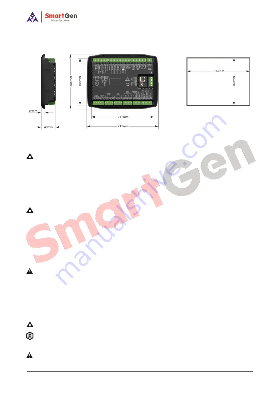
The controller is panel built-in design; it is fixed by clips when installed.
Fig. 17 Overall Dimension and Cutout Size
1)
Battery Voltage Input
NOTE:
HGM9520N controller can suit for wide range of battery voltage (8~35) VDC. Battery negative electrode must
be connected with the starter shell stably. The wire area connecting controller power B+/B- with negative and positive
electrodes mustn't be less than 2.5mm
2
. If floating charger is configured, please firstly connect output wires of charger
to battery’s positive and negative directly, and then connect wires from battery’s positive and negative to controller’s
positive and negative input ports separately in order to prevent the charger from disturbing the controller’s normal
working.
2)
Speed Sensor Input
NOTE:
Speed sensor is the magnetic equipment installed in the engine body to detect flywheel teeth number. The
wires used to connect with the controller shall be 2-core shielding wires. The shielding layer shall be connected to No. 18
terminal on the controller, and meanwhile the other terminal shall be hanging in the air. Another two signal wires shall be
connected to No.19 and No.20 terminals on the controller. The output voltage of the speed sensor shall be within (1~24)
VAC (effective value) in the range of full speed and 12VAC is recommended (at rated speed). As to speed sensor
installation, the sensor can firstly be spun to the connection flywheel, then invert 1/3 lap, and finally tighten up the screw
on the sensor.
3)
Output and Expand Relays
CAUTION:
All controller outputs are relay contact outputs. If the expansion relay is needed, freewheel diode (relay
coils is DC) and resistor and capacitor circuit (AC) shall be added to the two ends of the relay coils in order to prevent
disturbing the controller or others equipments.
4)
Alternate Current Input
Controller current input must be connected to outside current transformer. The secondary side current
of the current transformer must be 5A and at the same time current transformer phase and input
voltage phase must be correct, otherwise the collected current and active power are maybe not correct.
NOTE:
ICOM port must be connected to negative pole of battery.
WARNING!
When there is load current, transformer’s secondary side is prohibited open circuit.
5)
Withstand Voltage Test
CAUTION!
When controller had been installed in control panel, if need the high voltage test, please disconnect
controller’s all terminal connections, in order to prevent high voltage into controller and damage it.


