Cable layout and connections
67
851--164300 / C
Use the following procedure for connecting the cable C15 to the
Transceiver Unit. To ensure correct operation, tick of every item
when the action has been carried out.
1
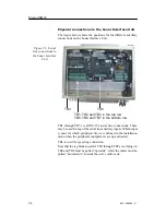
Use the cable gland on the right-hand side in the Transceiver
Unit as shown in the figure.
→
The cable glands at the bottom of the Transceiver Unit are
shown on figure 22 on page 64.
2
Terminate the cable’s shielding in the cable gland.
→
The cable shielding is shown in figure 23 on page 65.
3
Refer to cable connection drawing for termination to the
RJ45 plug and termination strip E201.
→
Refer to the cable information on page 161.
4
Connect the RJ45 plug to the front mounted socket of the
circuit board on the left side of the HV Power Unit.
C19 - AC power for hoist/lower motor
This cable is used for the 3-phase mains supply for the hoisting and
lowering motor on the Hull Unit. The cable’s specifications are
shown in the referenced cable drawing. The connections are made
to the Motor Control Unit.
→
Refer to the detailed cable drawing on page 165.
Observe the following procedure:
1
Set the hoisting/lowering switch S302 in the Motor Control
Unit to the
Stop
position.
2
Release the motor overload switch S301 in the Motor
Control Unit by pressing the red button labelled
0
.
3
Use the cable gland shown on the left-hand side of the figure
and terminate the cable shielding in the cable gland.
→
Refer to figure 24 on page 66 and figure 23 on page 65.
Caution
Note that the cables 17 and 19 must be separated inside the Motor
Control Unit. These cables must not be tied together.
4
Connect the 3-phase mains power cable directly to the motor
overload switch S301 according to the cable connection
drawing.
- The grounding wire should be attached to the ground
terminal beside the motor overload switch.
→
Refer to the detailed cable drawing on page 165.
5
Run the 3-phase mains power cable no. 19 from the Motor
Control Unit to the ship’s mains fuse board.
6
Disconnect the fuses and connect the 3-phase main cable to
the ship’s mains fuse board.
Содержание SH80 - REV C
Страница 2: ......
Страница 14: ...Simrad SH80 X 851 164300 C Blank page...
Страница 61: ...Transceiver unit 45 851 164300 C Figure 13 Mounting the Transceiver Unit CD3110A...
Страница 186: ...Simrad SH80 170 851 164300 C 12 3 Installation drawings The SH80 installation drawings are provided on the next pages...
Страница 195: ...Installation remarks 179 851 164300 C Party Date Signature Party Date Signature Party Date Signature...
Страница 196: ...Notes...
Страница 197: ...Notes...
Страница 200: ......


