


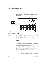


Cable layout and connections
65
851--164300 / C
2
Terminate the cable shielding.
→
Cable shielding is shown in figure 23.
Cable
main
screen
(CD3117)
Figure 23 Termination of
cable shielding
3
Terminate the cable pairs onto terminal block E201 in the
Transceiver Unit.
- For the insulation of the shielding of each of the cable
pairs, use part of the supplied cable sleeve.
→
Refer to the cable connection drawing on page 163 for
termination of the seven cable-pairs to terminal E201 in the
Transceiver Unit.
4
Run the cable from the Transceiver Unit to the Motor
Control Unit mounted on the gantry.
5
Use the cable gland on the right-hand side in the Motor
Control Unit, and terminate the cable shielding in the cable
gland.
→
The cable shielding is described in figure 23 on page 65.
→
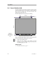
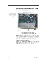
The interior of the Motor Control Unit is shown in figure
24.
6
Create a small cable slack inside the Motor Control Unit as
indicated in the figure.
7
Make the E301 connections in the Motor Control Unit
according to the cable connection drawing.
- Note that the shielding of each cable pair shall not be
connected in the Motor Control Unit.
Содержание SH80 - REV C
Страница 2: ......
Страница 14: ...Simrad SH80 X 851 164300 C Blank page...
Страница 61: ...Transceiver unit 45 851 164300 C Figure 13 Mounting the Transceiver Unit CD3110A...
Страница 186: ...Simrad SH80 170 851 164300 C 12 3 Installation drawings The SH80 installation drawings are provided on the next pages...
Страница 195: ...Installation remarks 179 851 164300 C Party Date Signature Party Date Signature Party Date Signature...
Страница 196: ...Notes...
Страница 197: ...Notes...
Страница 200: ......


