24
25
Before printing
Before printing
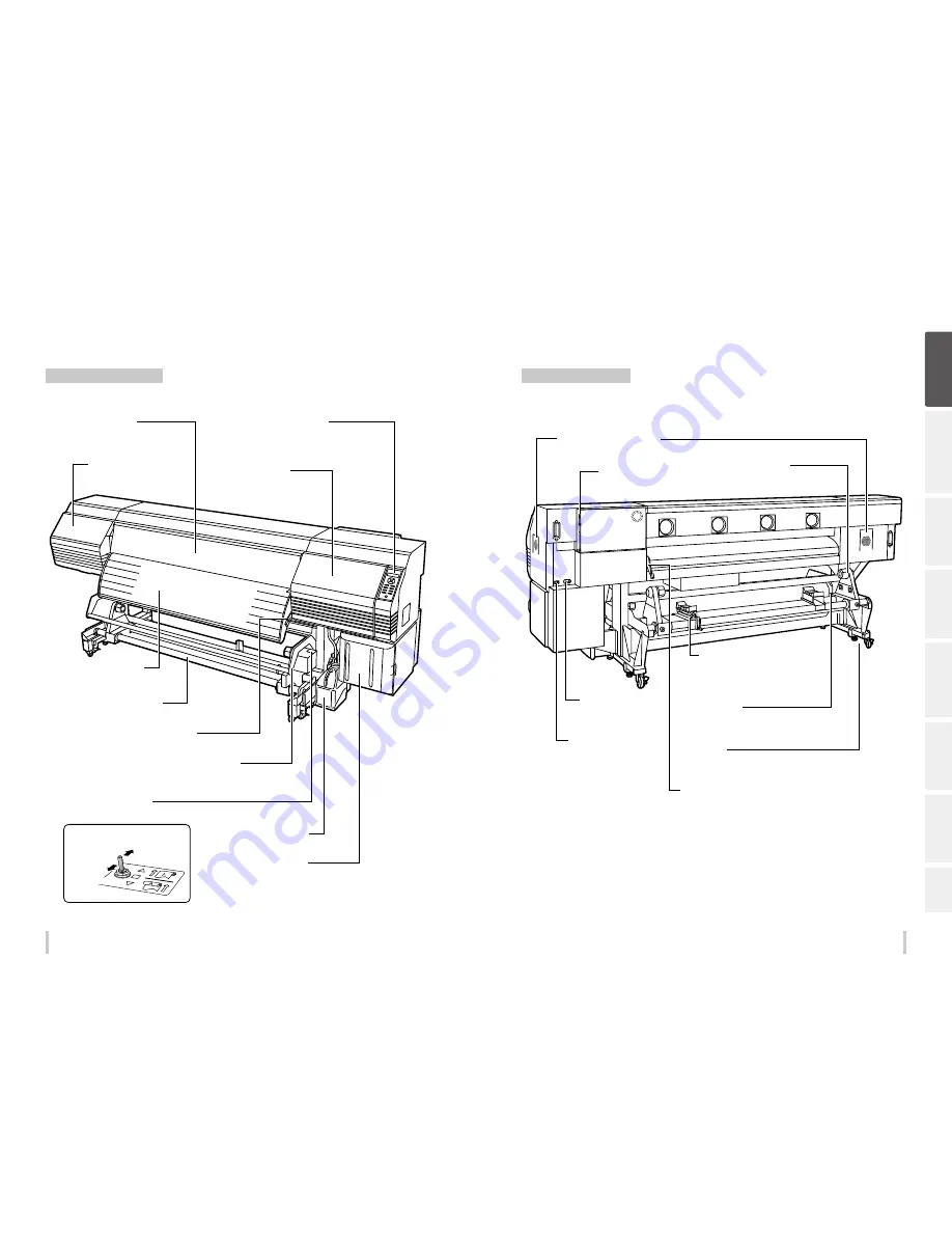
Appearance / Main components and their functions
Printer front (take-up side)
Printer rear (supply side)
Be
fo
re
p
rin
tin
g
Lo
adi
ng
the
m
edi
a
A
dj
us
tm
ent
M
ai
nt
enan
ce
A
dv
an
ce
d
op
er
ati
on
s
Trou
ble
sh
oo
tin
g
M
enu
tr
ee
Ap
pe
nd
ix
Waste ink bottle
Ink box
Open the cover to install the ink
cartridges.
Guide bar
Guides the media in loose mode.
Pressure roller lever
This lever fixes or releases the media.
Take-up direction switch
Sets the media take-up direction.
Take-up reel unit
Winds the printed media.
Output paper guide
Contains the after heater that dries ink.
Maintenance cover
Open to perform print head
maintenance.
Front cover
Must be closed during printing.
Capping cover
Opened when cleaning the capping
unit or the carriage.
Operation panel
Equipped with LEDs and LCD to display the
printer status, and keys to set functions.
Inner take-up
Winding off
Outer take-up
Pressure roller lever
A lever used to fixe or release the media.
Moves together with the pressure roller lever at the printer
front side.
Exhaust attachment (option)
Installation locations
Power inlet
Connect the power cable to
the power inlet.
Media stand
Temporarily supports the media during loading
and removal procedures.
Can be used also when moved to the TUR unit
side.
Media holder
To be installed at both ends of
the roll media.
Media jack
Lifts or lowers the media during loading and removal
procedures.
Can be used also when moved to the TUR unit side.
Caster
Set the lock to OFF when moving the printer and set
the lock to ON when locking the printer.
USB connector
Used to connect the printer to a
computer.
Printer power switch
Содержание IP-6620
Страница 112: ...222 ...


