


.
117. Assemble one Pushrod Connector into the engine’s throttle arm, and the other Pushrod Connector into the throttle servo
arm.
118.
Stiffen one end of the 1/16" dia. Steel Cable by flowing solder into it. Start by first coating the end of the Cable with
"soldering paste". Then heat the end of the Cable with a good hot soldering iron. When you think you’ve got the Cable hot
enough to melt the solder, touch the solder to the hot Cable (do not touch the solder to the soldering iron). The solder
should melt imediately and flow into the Cable. If it doesn’t, it means you didn’t get the Cable hot enough. Continue to heat
the Cable with the soldering iron until the Cable is hot enough to melt the solder. When you have approximately the first
2"-3" of the Cable filled with solder, let it cool completely. Then sand the soldered end smooth if necassary to remove any
lumps of solder.
119.
From the front of the airplane, slide the soldered end of the Cable into the Nylon Pushrod Tube that is glued in the firewall.
Slide it in until you can slip the soldered end of the Cable into the Pushrod Connector on the engine.
120.
Inside the fuselage, grab the end of the Steel Cable that is sticking out of the Nylon Pushrod Tube and try to work the
throttle. If it sticks or binds at the engine end, find the cause and fix it before going on to the next step. You may have to
put some slight bend(s) in the soldered portion of the cable to make it operate smoothly.
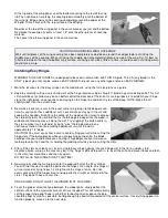
121.
Back inside the fuselage, mark the appropriate spot for cutting off the ends of both the Nylon Pushrod Tube and the Steel
Cable. Note that the Nyon Pushrod Tube should end in front of the throttle servo, while the Steel Cable should be long
enough to pass thru the Pushrod Connector on the throttle servo arm (see top view of full-size plan). Remove the Steel
Cable from the Nylon Pushrod Tube while you cut them both to length.
122.
Before sticking the Steel Cable back inside the Nylon Pushrod Tube, stiffen the servo end of the Cable in the same
manner you did the throttle end (Step 118). When cool, install the Cable inside the Nylon Tube for the final time, and
tighten down the Pushrod Connectors at both ends.
RECEIVER BATTERY PACK
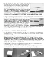
123.
Wrap the battery pack with a single layer of 1/4" thick soft foam rubber to insulate it from engine vibration and shock. Use
tape or rubber bands to hold the foam around the battery. Install the wrapped battery pack inside the nose of the model,
under the fuel tank floor, in the position shown on the plan (fuselage side view).
RECEIVER
124.
Drill a 1/16" dia. hole completely through the bottom of the fuselage in the area where the receiver will be located. This
hole is for the receiver antenna wire to exit the fuselage. Put a single drop of Thin CA glue around the edges of the hole to
keep the covering from coming loose. Let cure completely!
NOTE: These instructions describe running the antenna outside along the bottom of the fuselage. There are a lot of other
ways to handle the routing of a receiver antenna. If you prefer a different method, by all means use it. The main thing to
keep in mind is that you should always strive to keep the antenna as far away as possible from all the servo and battery
wires.
125.
Wrap the receiver with a single layer of 1/4" thick soft foam rubber to insulate it from engine vibration and shock. Use tape
or rubber bands to hold the foam around the receiver.
126.
Following the radio manufacturer’s instructions, plug all the wires for the servos, battery pack, and switch harness into the
receiver so the radio system is fully operational. Double check to be sure that each servo is plugged into its correct
receiver terminal and that it is responding properly.
NOTE: Since the receiver will be hard to get at, you should use a short "extension" wire (available from the radio
manufacturer) for the ailerons. Plug the extension wire into the receiver’s aileron terminal. Whenever you take the wing
on/off the model, you can connect/disconnect the ailerons at the plug-in between the extension wire and the servo wire,
leaving the extension wire itself permanently plugged into the receiver.
127.
Install the wrapped receiver inside the nose of the model, right behind the battery pack. Before you get the receiver
completely in place, poke the antenna wire down through the hole in the bottom of the fuselage (use an "antenna strain
relief" fitting if one came with your radio). Make sure the antenna wire is not tangled up in the servo and battery wires!
Continue pulling the antenna out the bottom of the fuselage as you slide the receiver forward against the battery pack. If
the receiver seems loose in the nose of the model, pack additional pieces of foam rubber around it to make sure it cannot
move around in flight.