


.
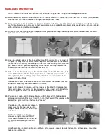
98. Screw one of the Nylon R/C Links onto the threads remaining outside the nylon pushrod tube. Screw it halfway onto the
exposed threads - until there are the same amount of exposed threads in front and in back of the R/C Link.
99.
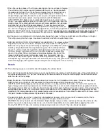
Slide the rudder pushrod (from the rudder end) inside the larger nylon pushrod tube that is already in the fuselage. Slide it in
until the nylon R/C link is even with the rudder control horn. Pry open the R/C link, clip it into the outermost hole of the
control horn, and then snap it shut. Now reach into the fuselage and try operating the rudder pushrod from the servo end. It
should work smooth and easy. If not, figure out why and fix it.
100.
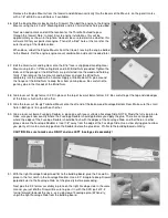
Set the rudder in neutral position. Mark the servo end of the Small (inner) Nylon Pushrod Tubing exactly 2-3/8" from the
hole in the rudder servo arm. Cut off the nylon tube at the mark.
101.
Cut another 10" Threaded Steel Rod to 2-1/2" overall length. Cut off the plain end of the rod, not the threaded end! Solder a
2-56 Solder Clevis to the smooth end of the rod. Screw the threaded end of the rod completely into the end of the inner
Nylon Pushrod Tube. Then connect the Solder Clevis to the servo arm.
102.
Using the leftover cutoff wire from the previous step, make a pushrod to run from the opposite side of the rudder servo arm
back to the plywood Tiller Bar. Bend the wire according to the full-size pattern shown at the bottom left corner of this page.
103.
104.
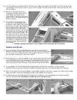
Assemble a Pushrod Connector in the innermost hole of the rudder servo control arm.
NOTE: A Pushrod Connector consists of a brass Connector body, a 4-40 Set Screw, and a Nylon
Retainer .
Install the Tiller Bar Pushrod in the Pushrod Connector and Tiller Bar (see full-size plan). Put the
90° bend of the pushrod in the hole in the plywood Tiller Bar - the other end in the Pushrod
Connector on the rudder servo arm.
105.
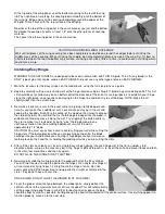
Temporarily plug the rudder servo into the receiver and
testthe operation of the rudder. If you sense any binding in
the rudder movement, find the cause and fix it now. With full
right and left movement of the transmitter’s rudder control
stick, the rudder should move approximately 1" right and 1"
left.
NOTE: If you are not getting the correct amount of rudder travel, try moving the nylon R/C link to a different hole in the
servo arm. Also, fine tune the overall length of the rudder pushrod, by screwing one or both of the nylon R/C links further in
or out, until the rudder is exactly neutral when the transmitter stick (and trim lever) is neutral.
106.
Complete the installation of the steerable tailwheel by assemblying the Tailwheel
Wire (w/Wheel), the Tailwheel Steering Arm, and two 1/16" Wheel Collars into the
Tailwheel Bracket as shown on the plan. After the parts are secured, turn on the
radio, center the rudder servo and the tailwheel, and then crimp the ends of the
steering cables to the tailwheel steering arm with the aluminum tubes provided.
ELEVATOR CONTROL
107.
Construct and install the Elevator Pushrod, using previous Steps 95 thru 101 as a guide (simply subsitute the word
"elevator" whenever the word "rudder" is used in those steps).