


.
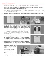
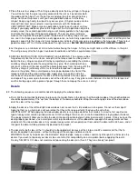
91. Place the Fin/Rudder assembly on the fuselage, sticking the leading edge of the fin through the hole in the top of the fuse.
Carefully line up the trailing edge of the fin using the center-line on top of the stab as a guide. Draw along both sides of the
fin, marking its location on the top of the fuselage and stab. Take the Fin/Rudder assembly off the fuse and strip away the
covering material inside the lines.
92.
Gluing the Fin to the Fuselage: Apply a
coat of Thick CA glue to the area where
the Fin will go. Remount the Fin onto the
fuselage, line it up as before, and hold it
firmly in place until the glue dries. Hold a
90 degree triangle against the Fin to
insure that it cures perpendicular to the
stab.
Radio Installation
NOTE: The receivers and servos of different brand radios are not all the same size! Consequently, it is practically impossible
for us to guarantee that every word and picture in this next sequence will pertain exactly to your installation. As you go
along, you may notice some differences between your radio equipment and ours! Nonetheless, most of the radio system
components will be close enough in size and appearance that you should be able to figure out for yourself how to handle
any minor differences. Follow the instructions as closely as possible. If you have any questions, seek the advice of an
experienced modeler. The installation of the control system in your new model is very important! It must be done correctly in
order for your airplane to fly successfully and safely.
MOUNTING THE FUSELAGE SERVOS
93.
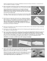
Locate the laser-cut plywood servo tray. Mount your throttle, elevator, and rudder servos in the tray using the screws,
washers, and rubber grommets that came with your radio system. Be sure to orient the servos in the tray as shown in the
fuselage top view.
CAUTION: The rubber grommets act as shock absorbers and prevent engine
vibration from damaging the electronics in the servos. Do not over tighten the
servo mounting screws to the point where they compress the rubber grommets so
far that all shock absorbing ability is lost. Tighten the screws just enough to make
contact with the grommets and keep the servos in place.
94.
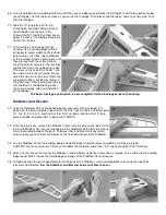
Set the servo tray in place inside the fuselage, on the "shelf" made by the fuselage
doublers. Slide the servo tray as far forward as you can. Flow Medium CA glue into
the joints between the edges of servo tray and the fuselage sides. Be careful to not
get any glue on the servos or servo wires.
RUDDER AND TAILWHEEL CONTROL
95.
Locate the Small Nylon Control Horn (the one with 4 holes) and two #2 x 1/2"
Sheet Metal Screws for the Rudder. Cut the Control Horn and the Retainer Plate
apart. Hold the Control Horn in exact position (see plan) on the right side of the
rudder and mark the location of the mounting holes. Drill pilot holes through the
rudder with a 1/16" dia. drill bit (turn the bit with your fingers, a drill is not
necessary). Mount the Control Horn onto the rudder with the Sheet Metal Screws
and Retainer Plate.
NOTE: Turn the screws down until both the control horn and retainer plate make
firm contact with the balsa. Then, turn each screw in 1/2 turn further. By tightening
the screws in this manner, the control horn will not crush the balsa.
96.
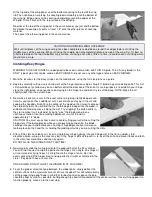
Cut one of the 10" Threaded Steel Rods to 7" overall length. Cut off the plain end
of the rod, not the threaded end!
97.
Locate one piece of Small Nylon Pushrod Tubing (1/8" O.D. x 36" long). Slide the
plain end of the 7" long threaded steel rod inside the tubing up to the beginning of
the threads. Now get a good grip on the threaded portion of the steel rod on the
nylon tube and start screwing the threads into the tubing. Keep turning the rod until
a MINIMUM of 1/8" of threads are inside the nylon tubing (3/16" is even better).