


.
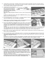
Remove the Engine Mounts from the firewall and drill down vertically thru the beams of the Mounts, on the pencil marks,
with a 1/8" drill bit (use a drill press if available).
46.
Bolt the Engine Mounts back onto the Firewall. Then bolt the engine to the Engine
Mounts using the 4-40 x3/4" Mounting Bolts and 4-40 Aircraft Lock Nuts provided.
Next we need to mark and drill the location for the Throttle Pushrod to pass
through the firewall. Note: In most 2-cycle engine installations, this will be
approximately as shown in the photo. However be sure to determine whether this
will work OK for your particular engine. Then drill a 9/64" hole at this mark for the
outer housing of the flexible cable.
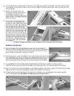
When done, unbolt the Engine Mounts from the firewall, leaving the engine bolted
to the Mounts. Set the engine/engine mount combination aside until needed later.
47.
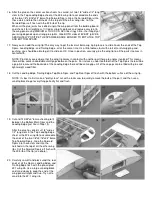
Bolt the Aluminum Landing Gear onto the 3/16" laser-cut plywood Landing Gear
Mount using 4-40 x1/2" Mounting Bolts and 4-40 Blind Nuts provided. Tighten the
Bolts until the prongs of the Blind Nuts are just started into the wood and holding
firmly. Then remove the Aluminum Landing Gear and seat the Blind Nuts
completely into the wood with a hammer. Apply a little Medium CA glue around
the flanges of the Blind Nuts to keep them from coming loose. Be careful not to
get any glue in the threads of the Blind Nuts.
48.
Glue laser-cut lite-ply former F-2D in place at the top of lasercut balsa former F-2. Be careful to get the top and side edges
of the formers flush with each other.
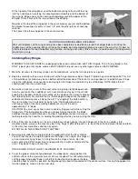
49.
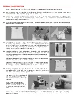
Glue the laser-cut lite-ply Tailwheel Mount onto the aft end of the balsa wood Fuselage Bottom Rear. Make sure the small
hole in both parts line up with each other.
50.
Glue a laser-cut balsa Fuselage Doubler in place on each laser-cut balsa Fuselage Side. NOTE: Study the full-size plan to
make sure you know exactly where the Fuselage Doubler should go before you apply the glue. There are some places
where the edges of the Fuselage Doubler should be flush with the edges of the Fuselage Side, and that there are other
places where the Fuselage Doubler is inset 1/8" away from the edge of the Fuselage Side. Use a slow drying glue to allow
you plenty of time to accurately position the Doubler before the glue dries. Pin flat to the building board until dry.
CAUTION: Be sure to make one RIGHT and one LEFT fuselage side assembly!
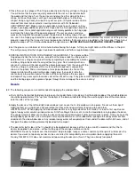
51.
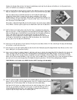
With the right Fuselage Side pinned flat to the building board, glue the Firewall in
place in the first notch in the Fuselage Doubler. Use a 90° triangle to keep Firewall
perpendicular to the Fuselage Side. Let the glue dry before proceeding.
Next glue the F-2 former assembly in place on the right Fuselage side in the same
manner you just did the Firewall. Be sure to glue it in with the F-2D part of F-2
facing forward (towards the nose - see side view of Fuselage plan.) When dry,
unpin the right Fuselage Side from the building board.