


.
Final Assembly
83.
Insert the two 1/4" x 4-3/4" hardwood
dowels through the holes in the
fuselage. The dowels should protrude
11/16" from each side of the fuselage.
Glue the dowels in place.
Paint the exposed portion of the dowels
with a couple coats of fuelproof paint.
Let dry.
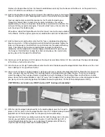
84.
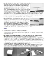
Mount the wing on the fuselage with two #67 rubber bands. Using a tape measure, carefully measure from the fuselage
sides out to the wing tips (measurement A ) to be sure that the wing is centered on the fuselage. Now, measure from the
wing tips back to the tail end of the fuselage (measurement B ) to make sure the wing is square with the fuselage. Once the
wing is properly located, put some line-up marks on both the wing and fuselage so that you can easily re-locate the wing the
next time you put it back on the fuselage.
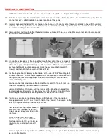
85.
Put a center mark on the top of the
fuselage, right above former F-6. Also
put a center mark on the front of the
Stabilizer. Using no glue, trial fit the
Stabilizer onto the fuselage. Line up the
center marks at the front and use one T-
Pin to secure the front of the stab, as
shown. Push the pin completely through
the stab and into the fuselage, to secure
it in position.
86.
Carefully measure from the stab tips to the fuselage front (measurement C ), to make sure the Stabilizer is square with the
fuselage. Pivot the back of the stab until both measurements are exactly the same! Now, push another T-Pin through the
stab, into the fuselage, to secure it in position.
87.
Lift the rear of the fuselage up, without jarring the stab loose, to enable you to mark the location of both fuselage sides on
the bottom of the stab with a pencil.
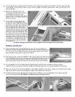
88.
Remove the stabilizer from the fuselage and very carefully strip away the covering material on the bottom, between the two
lines, where the stab will be glued to the fuselage. CUT THE COVERING LIGHTLY ALONG THE LINES! AVOID CUTTING
THE WOOD UNDERNEATH THE COVERING MATERIAL! HINT: For a better finished appearance, cut about 1/32 inside
the lines so that the stab covering will appear to tbuec ked inside the glue joint.
89.
Gluing the Stabilizer to the Fuselage: First apply a coat of SIG Epoxy or Thick CA glue to the area of the fuselage where the
Stabilizer will go. Use enough glue to completely wet the entire surface of the joint. Quickly remount the stab onto the
fuselage, using the edges of the cutaway covering on the bottom to get the stab back into correct alignment on the
fuselage. Press the Stab down firmly into contact with the fuse while you wipe off any excess glue that oozes out of the joint
with a rag. Hold tight until the glue cures.
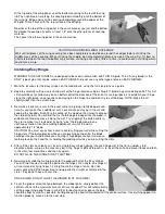
90.
Draw a center-line on top of the stab, running from the center mark above F-6 to a point above the rear of the fuselage.
NOTE: In the photo you ll see that we have temporarily stuck a T-Pin through the hinge gap to give us a visual alignment
with the middle of the end of the fuselage. Use a straight edge to draw the line from the mark above F-6 to the pin.