


.
108. When finished, temporarily plug the
elevator servo into the receiver and test
the operation of the elevator. If you
sense any binding in the elevator
movement, find the cause and fix it
now. With full up and down movement
of the transmitter’s elevator control
stick, the elevator should move
approximately 9/16" up and 9/16" down.
NOTE: If you are not getting the correct amount of elevator travel, try moving the nylon R/C link to a different hole in the
servo arm. Also, fine tune the overall length of the elevator pushrod, by screwing one or both of the nylon R/C links further
in or out, until the elevator is exactly neutral when the transmitter stick (and trim lever) is neutral.
AILERON CONTROL
109.
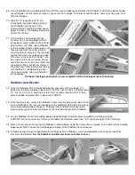
Mount your aileron servo in plywood tray which is already installed on the bottom of the wing. REMEMBER: Do not over
tighten the servo mounting screws to the point where they compress the rubber grommets too far.
110.
Locate the Nylon Aileron Connectors and cut them apart. Thread one Nylon Aileron Connector onto the end of each
Aileron Torque Rod. Screw the connectors on until they are about 1/8" past the tip of the torque rods (see Plan Sheet 1,
Fuselage Side View).
111.
The aileron pushrods are made from two 10" Threaded Steel Rods. Screw a Nylon R/C Link halfway onto the threaded end
of each rod. Then clip the R/C Links into the holes in the Nylon Aileron Connectors and line up the pushrods with the servo
arms.
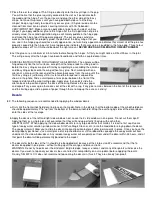
112.
Tape the ailerons in neutral position (the bottom of the ailerons and the wing
should be flush). Mark and cut the plain end of the pushrod wires 5/8" short of the
holes in the aileron servo arm.
113.
Solder an R/C Solder Link onto the end of each pushrod wire. NOTE: It’s best to
take the pushrods off for soldering. You wouldn’t want to drop a piece of hot
solder and burn a hole through the wing. Also, make sure the pushrod wire sticks
completely inside the barrel of the solder link.
114.
When done soldering, untape the ailerons and install the aileron pushrods
between the servo and the torque rods. It will probably be necessary to re-adjust
the overall length of the aileron pushrods. Screw the Nylon R/C Links further in or
out, to get both ailerons into neutral position at the same time make sure the
aileron servo is neutral while doing this.
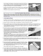
115.
Temporarily plug the aileron servo into the receiver and test the operation of the
ailerons. If you sense any binding in the aileron movement, find the cause and fix
it now. With full right and left movement of the transmitter’s aileron control stick,
the ailerons should move approximately 3/8" up and 3/8" down.
NOTE: If you are not getting the correct amount of aileron travel, try moving the nylon R/C links to a different hole in the
servo arm. You can also screw the Aileron Connectors up or down on the Torque Rods to increase or decrease the
amount of travel.
THROTTLE PUSHROD
116.
Materials are provided for making a "flex-cable type" throttle pushrod. This type of pushrod is semi-flexible, which means it
can be bent in gradual flowing curves if necessary to make its ends line up with both the engine’s throttle arm and the
throttle servo. The Throttle Pushrod consists of: one 1/8" o.d. piece of Small Nylon Pushrod Tubing (already glued into the
firewall back in Step 70); one 1/16" dia. x 18" Steel Cable; and two Pushrod Connectors.