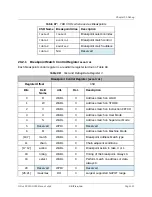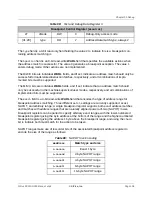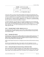
The high nibble of
tdata1
contains a 4-bit
type
code that is used to identify the type of TDR
selected by
tselect
. The currently defined
types
are shown below:
Table 96:
tdata
Types
Type
Description
0
No such TDR register
1
Reserved
2
Address/Data Match Trigger
≥ 3
Reserved
The
dmode
bit selects between debug mode (
dmode
=1) and machine mode (
dmode
=1) views of
the registers, where only debug mode code can access the debug mode view of the TDRs. Any
attempt to read/write the
tdata1-3
registers in machine mode when
dmode
=1 raises an illegal
instruction exception.
20.1.3
Debug Control and Status Register (
dcsr
)
This register gives information about debug capabilities and status. Its detailed functionality is
described in
The RISC‑V Debug Specification 0.11
.
20.1.4
Debug PC
dpc
When entering debug mode, the current PC is copied here. When leaving debug mode, execu-
tion resumes at this PC.
20.1.5
Debug Scratch
dscratch
This register is generally reserved for use by Debug ROM in order to save registers needed by
the code in Debug ROM. The debugger may use it as described in
The RISC‑V Debug Specifi-
cation 0.11
.
20.2
Breakpoints
The FE310-G000 supports two hardware breakpoint registers per hart, which can be flexibly
shared between debug mode and machine mode.
When a breakpoint register is selected with
tselect
, the other CSRs access the following infor-
mation for the selected breakpoint:
Chapter 20 Debug
SiFive FE310-G000 Manual: v3p2
© SiFive, Inc.
Page 106
Содержание FE310-G000
Страница 1: ...SiFive FE310 G000 Manual v3p2 SiFive Inc ...

