


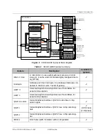


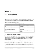


FE310G-0000
E31 Core Complex
GPIO Complex
Always-On Domain
P
-B
us:
T
ile
Link
B
32
D
32
QSPI0
Real-Time Clock
Platform-Level
Interrupt Control
TAPC
Debug Module
Debug RAM (28B)
Instruction Fetch
RV32IMAC
Branch Prediction
Inst. Decompressor
Instruction Bu
ff
er
M
M
Load/Store
dip
eip
sip
Instruction Cache
(16KiB, 2-way)
Instruction Cache Ref ll M
OTP (8KiB)
Data SRAM (16KiB)
UART0
QSPI1
M
JTAG
1.8V AON Core
erst_n
QSPI Flash
GPIO
Multiplier/Divider
Watchdog
Core-Local Interrupt
Control
Real-Time Clock Ticks
Backup Registers
PMU
Reset Unit
dwakeup_n
1.8V AON Pads
pmu_out_0
LFROSC
Mask ROM (8KiB)
Clock Generation
HFXOSC
PLL
HFROSC
vddpll
vsspll
hfxoscin
hfxoscout
UART1
PWM0 (8-bit)
PWM1 (16-bit)
QSPI2
C-
B
us:
T
ile
Link
B
32
D
32
A
-B
us:
T
ile
Link
B
4
D
32
M
hfclkrst
rtccmpip
wdogcmpip
Global
Interrupts
1.8V MOFF Core
3.3V MOFF Pads
Core Reset Sync
corerst
pmu_out_1
psdlfaltclk
psdlfaltclksel
PWM2 (16-bit)
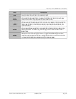
Figure 1:
FE310-G000 top-level block diagram.
Table 1:
FE310-G000 Feature Summary.
Feature
Description
Available in
QFN48
RISC-V Core
1× E31 RISC‑V cores with machine mode only, 16 KiB
2-way L1 I-cache, and 16 KiB data tightly integrated mem-
ory (DTIM).
✔
Interrupts
Software and timer interrupts, 51 peripheral interrupts con-
nected to the PLIC with 7 levels of priority.
✔
UART 0
Universal Asynchronous/Synchronous Transmitters for
serial communication.
✔
UART 1
Universal Asynchronous/Synchronous Transmitters for
serial communication.
QSPI 0 Control
Serial Peripheral Interface. QSPI 0 Control has 1 chip
select signal.
✔
QSPI 1
Serial Peripheral Interface. QSPI 1 has 4 chip select sig-
nals.
✔
(3 CS lines)
(2 DQ lines)
QSPI 2
Serial Peripheral Interface. QSPI 2 has 1 chip select sig-
nal.
PWM 0
8-bit Pulse-width modulator with 4 comparators.
✔
Chapter 1 Introduction
SiFive FE310-G000 Manual: v3p2
© SiFive, Inc.
Page 9
Содержание FE310-G000
Страница 1: ...SiFive FE310 G000 Manual v3p2 SiFive Inc ...