


When used to drive the PLL, the 16 MHz crystal oscillator output frequency must be divided by
two in the first-stage divider of the PLL (i.e.,
) to provide an 8 MHz reference clock to the
VCO.
The input pad of the HFXOSC can also be used to supply an external clock source, in which
case, the output pad should be left unconnected.
The HFXOSC input can be used to generate
hfclk
directly if the PLL is set to bypass.
The HFXOSC is controlled via the memory-mapped
hfxosccfg
register.
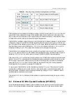
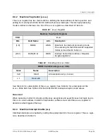
hfxosccfg: Crystal Oscillator Configuration and Status (
hfxosccfg
)
Register Offset
0x4
Bits
Field Name
Attr.
Rst.
Description
[29:0]
Reserved
30
hfxoscen
RW
0x1
Crystal Oscillator Enable
31
hfxoscrdy
RO
X
Crystal Oscillator Ready
The
hfxoscen
bit turns on the crystal driver and is set on wakeup reset, but can be cleared to
turn off the crystal driver and reduce power consumption. The
hfxoscrdy
bit indicates if the
crystal oscillator output is ready for use.
The
hfxoscen
bit must also be turned on to use the HFXOSC input pad to connect an external
clock source.
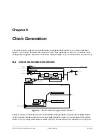
6.5
Internal High-Frequency PLL (HFPLL)
The PLL generates a high-frequency clock by multiplying a mid-frequency reference source
clock, either the HFROSC or the HFXOSC. The input frequency to the PLL can be in the range
6–48 MHz. The PLL can generate output clock frequencies in the range 48–384 MHz.
The PLL is controlled by a memory-mapped read-write
pllcfg
register in the PRCI address
space. The format of
pllcfg
is shown in Table 7.
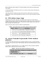
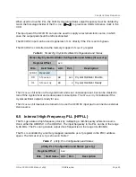
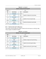
pllcfg: PLL Configuration and Status (
pllcfg
)
Register Offset
0x8
Bits
Field Name
Attr.
Rst.
Description
Table 6:
hfxosccfg: Crystal Oscillator Configuration and Status
Table 7:
pllcfg: PLL Configuration and Status
Chapter 6 Clock Generation
SiFive FE310-G000 Manual: v3p2
© SiFive, Inc.
Page 25
Содержание FE310-G000
Страница 1: ...SiFive FE310 G000 Manual v3p2 SiFive Inc ...