19.9
Generating Left- or Right-Aligned PWM Waveforms
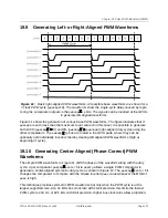
Figure 11:
Basic right-aligned PWM waveforms. All possible base waveforms are shown for a
7-clock PWM cycle (
pwmcmp0
=6). The waveforms show the single-cycle delay caused by regis-
tering the comparator outputs in the
pwmcmp
ip
bits. The signals can be inverted at the GPIOs
to generate left-aligned waveforms.
Figure 11 shows the generation of various base PWM waveforms. The figure illustrates that if
pwmcmp0
is set to less than the maximum count value (6 in this case), it is possible to generate
both 100% (
pwmcmp
0) and 0% (
pwmcmp
pwmcmp0
) right-aligned duty cycles using the
other comparators. The
pwmcmp
ip
bits are routed to the GPIO pads, where they can be
optionally and individually inverted, thereby creating left-aligned PWM waveforms (high at
beginning of cycle).
19.10
Generating Center-Aligned (Phase-Correct) PWM
Waveforms
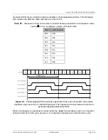
The simple PWM waveforms in Figure 11 shift the phase of the waveform along with the duty
cycle. A per-comparator
pwmcmp
center
bit in
pwmcfg
allows a single PWM comparator to
generate a center-aligned symmetric duty-cycle as shown in Figure 12. The
pwmcmp
center
bit
changes the comparator to compare with the bitwise inverted
pwms
value whenever the MSB of
pwms
is high.
This technique provides symmetric PWM waveforms but only when the PWM cycle is at the
largest supported size. At a 16 MHz bus clock rate with 16-bit precision, this limits the fastest
PWM cycle to 244 Hz, or 62.5 kHz with 8-bit precision. Higher bus clock rates allow proportion-
Chapter 19 Pulse Width Modulator (PWM)
SiFive FE310-G000 Manual: v3p2
© SiFive, Inc.
Page 101
Содержание FE310-G000
Страница 1: ...SiFive FE310 G000 Manual v3p2 SiFive Inc ...

