


8.3.2
Machine Trap Vector (
mtvec
)
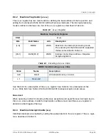
The
mtvec
register has two main functions: defining the base address of the trap vector, and
setting the mode by which the FE310-G000 will process interrupts. The interrupt processing
mode is defined in the lower two bits of the
mtvec
register as described in Table 14.
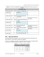
Table 13:
mtvec
Register
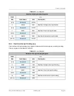
Machine Trap Vector Register
CSR
mtvec
Bits
Field Name
Attr.
Description
[1:0]
MODE
WARL
MODE
Sets the interrupt processing mode.
The encoding for the FE310-G000 supported
modes is described in Table 14.
[31:2]
BASE[31:2]
WARL
Interrupt Vector Base Address. Requires
64-byte alignment.
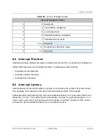
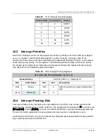
Table 14:
Encoding of
mtvec.MODE
MODE Field Encoding
mtvec.MODE
Value
Name
Description
0x0
Direct
All exceptions set
pc
to
BASE
≥ 1
Reserved
See Table 13 for a description of the
mtvec
register. See Table 14 for a description of the
mtvec.MODE
field. See Table 18 for the FE310-G000 interrupt exception code values.
Mode Direct
When operating in direct mode all synchronous exceptions and asynchronous interrupts trap to
the
mtvec.BASE
address. Inside the trap handler, software must read the
mcause
register to
determine what triggered the trap.
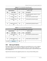
8.3.3
Machine Interrupt Enable (
mie
)
Individual interrupts are enabled by setting the appropriate bit in the
mie
register. The
mie
regis-
ter is described in Table 15.
Chapter 8 Interrupts
SiFive FE310-G000 Manual: v3p2
© SiFive, Inc.
Page 36
Содержание FE310-G000
Страница 1: ...SiFive FE310 G000 Manual v3p2 SiFive Inc ...