Advanced commissioning
7.6 Basic positioner and position control
Converter with control units CU250D-2
194
Operating Instructions, 04/2015, FW V4.7.3, A5E34261542B AB
Procedure
To set the flying referencing, proceed as follows:
1.
Set with which edge of the reference cam signal the converter references its position
actual value:
0: Rising edge
1: Falling edge
2.
Interconnect the switchover of reference cams 1 and 2 with a signal of your choice.
3.
Select the digital input with which reference cam 1 is interconnected.
4.
Select the digital input with which reference cam 2 is interconnected.
Several reference points:
If you require several reference points for an axis, then you must do the following:
–
Assign the corresponding digital input to the respective reference point.
–
Change the reference point coordinate during operation, e.g. using the non-cyclic
communication of the fieldbus.
5.
Set the inner window for referencing. You deactivate the inner window with the value 0.
6.
Set the outer window for referencing. You deactivate the outer window with the value 0.
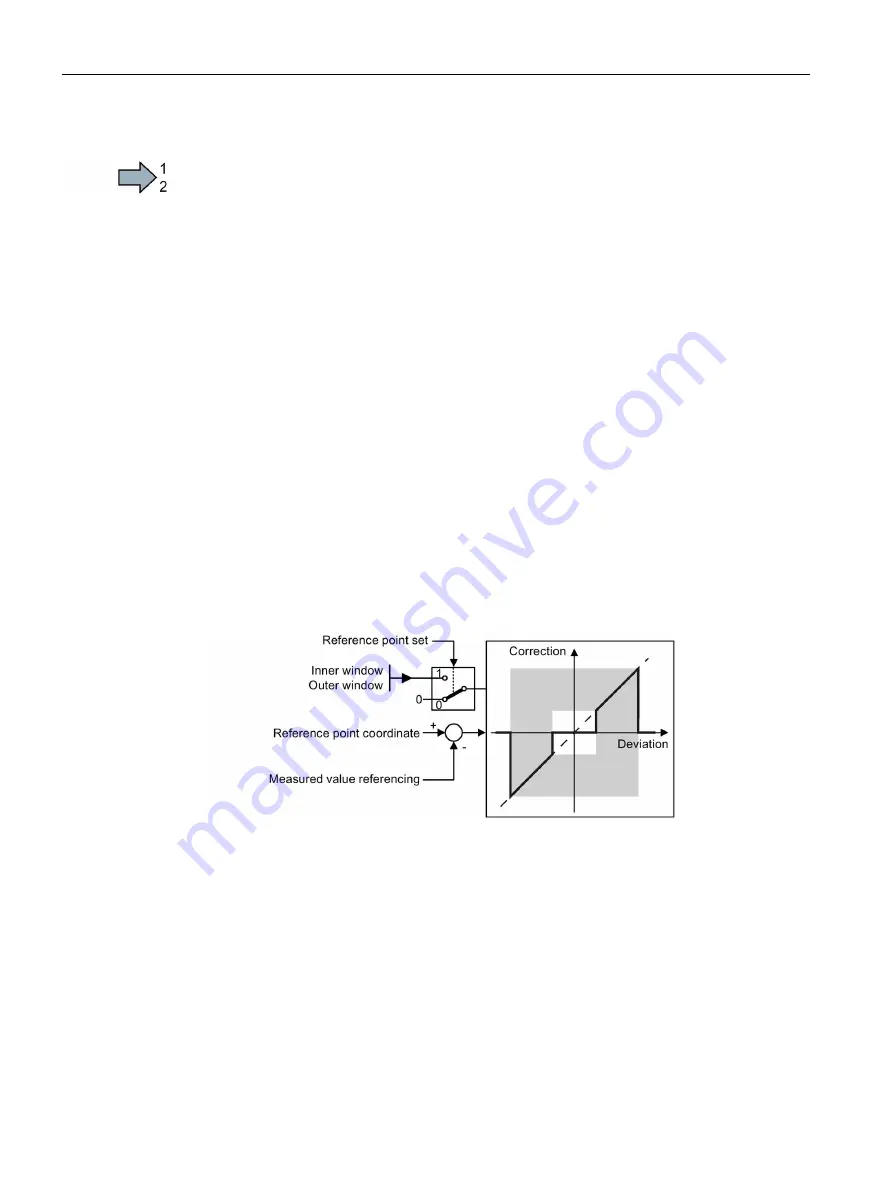
Referencing can be suppressed depending on the deviation of the actual position value:
Inner window: For excessively small deviations, the converter does not correct its position
actual value.
Outer window: The converter signals an excessive deviation, but does not correct its
position actual value.
Figure 7-39 Outer and inner window for flying referencing
7.
Specify the following:
–
Taking into account the offset in traversing distance: The converter corrects both the
actual position as well as the setpoint. The relative traversing distance is shorter or
longer by the value of the correction.
Example: 500 LU is the axis start position. The axis should travel relatively through
1000 LU. The converter corrects the reference point during travel by 2 LU, and travels
to the corrected target position 1498 LU.
–
Not taking into account the correction in the traversing distance: The converter
corrects both the actual position as well as the setpoint. The relative travel distance
remains unchanged.
Example: 500 LU is the axis start position. The axis should travel relatively through


