Appendix
A.4 Setting a non standard HTL encoder
Converter with the control units CU240D-2
336
Operating Instructions, 04/2018, FW V4.9 SP10, A5E34262100B AF
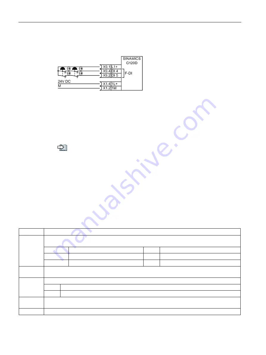
You may connect emergency stop control devices in series because it is not possible for
these devices to fail and be actuated at the same time.
Figure A-7 Connecting electromechanical sensors in series
According to IEC 62061 (SIL) and ISO 13849-1 (PL), position switches of protective doors
may also connected in series.
Exception: If several protective doors are regularly opened at the same time, it is not
possible for faults to be detected, which means that the position switches must not be
connected in series.
You can find additional connection options in the "Safety Integrated" Function Manual:
Overview of the manuals (Page 343)
A.4
Setting a non standard HTL encoder
Proceeding: manually configuring the encoder
1.
Set p0010 = 4.
This allows the encoder parameters to be accessed.
2.
Configure the encoder using the table below.
3.
Set p0010 = 0.
Parameter Description
p0400[0]
Encoder type selection (Factory setting: 0)
Selects the encoder from the list of encoder types supported by the firmware of the Control Unit.
0
No encoder
3005
1024 HTL A/B without zero mark
3001
1024 HTL A/B with zero mark
3007
2048 HTL A/B without zero mark
3003
2048 HTL A/B with zero mark
9999
User-defined
p0408[0]
Rotary encoder pulse No. (Factory setting: 2048)
Sets the number of encoder pulses.
p0410[0]
Encoder inversion actual value (Factory setting: 0000 bin)
Bit 00 1 signal: Invert speed actual value
Bit 01 Not relevant for the CU240D-2
p0425[0]
Encoder, rotary zero mark distance (Factory setting: 2048)
Sets the distance in pulses between two zero marks. This information is used for zero mark monitoring.
p0430[0]
Sensor Module configuration (Factory setting: 0000 0000 0000 0000 0000 0000 0000 0000 bin)


