Configuration
03/03
CP 243-1 IT
J31069-D0429-U001-A0-7618
76
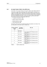
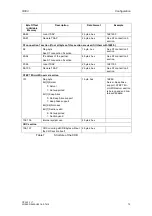
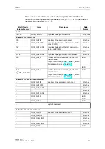
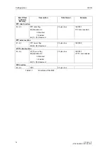
Byte Offset in
Variable Memory
Name
Description
Data
Format
... ...
ASCII
... COM_CHr_p
ASCII
CRC section
The last two bytes
of the NDB
CRC for all NDB
bytes without the
CRC section itself
2 bytes, hex
The last two
bytes of the
NDB
Table 9
Structure of the NDB
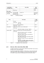
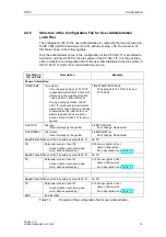
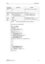
Name
Description
Data
Format
<op>
Job type
Value range: R for read
W
for
write
ASCII
<cnt>
Number of bytes to be transferred
Value range: 1 to 212
ASCII
<local_buffer>
Address of the memory area in the local system
Value range:
VB0 to VBx, whereby x is the max. V address
ASCII
<remote_buffer>
Address of the memory area on the communication partner
Value range:
IB0 to IBx, whereby x is the max. input address
(S7-200 / S7-300 / S7-400)
QB0 to QB, whereby x is the max. output address
(S7-200 / S7-300 / S7-400)
MB0 to MBx, whereby x is the max. marker address
(S7-200 / S7-300 / S7-400)
VB0 to VBx, whereby x is the max. variable address
(S7-200)
DB0.DBB0 to DBx.DBBy, whereby x is the max DB
number, and y is the highest address in the data block
within the DB (S7-300 / S7-400)
ASCII
Table 10
Configuration of the read/write jobs
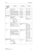
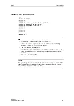
4.4.5
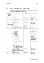
Structure of the Internet Data Block (IDB)
The IDB is created by the Internet wizard in STEP 7 Micro/WIN 32. The structure of
the IDB is shown in the following table.
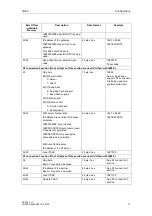
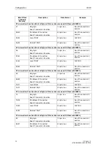
The IDB immediately follows the NDB in variable memory. Since the length of the
NDB varies with the current configuration, no general start address can be given
for the IDB. The byte offsets in the table below all refer to this start address.
Содержание CP 243-1 IT
Страница 46: ...Installation and Commissioning 03 03 CP 243 1 IT J31069 D0429 U001 A0 7618 46 ...
Страница 94: ...Programming 03 03 CP 243 1 IT J31069 D0429 U001 A0 7618 94 ...
Страница 106: ...Diagnosis 03 03 CP 243 1 IT J31069 D0429 U001 A0 7618 106 ...
Страница 120: ...Technical Data 03 03 CP 243 1 IT J31069 D0429 U001 A0 7618 120 ...
Страница 130: ...Example 03 03 CP 243 1 IT J31069 D0429 U001 A0 7618 130 ...


