03/03
Installation and Commissioning
CP 243-1 IT
J31069-D0429-U001-A0-7618
51
3.3
Installation in a Control Panel
What to do/steps
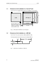
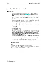
1. Bore holes for the DIN M4 screws on the control panel. Read and follow the
notes and dimensions given in chapters 3 and 3.1 on installation in a control
panel.
2. With horizontal installation to the right next to the CPU and with vertical installa-
tion above the CPU, screw the CP 243-1 IT to the control panel. Use DIN M4
screws.
3. Insert the ribbon cable of the CP 243-1 IT in the connection provided under the
front covering flap of the adjacent module or the S7-200 CPU. The shape of the
plug connector prevents it from being incorrectly inserted.
4. Connect the grounding terminal.
Connect the grounding terminal of the CP 243-1 IT with the next available
ground to obtain the highest possible interference immunity. We recommend
connecting all grounding terminals individually. Use lines with a cross section of
1.5 mm
2
for this.
5. Connect the power supply.
6. Connect the Ethernet cable.
The transmission medium is a 2 x 2-core, twisted pair, shielded line with a ripple
resistance of 100 Ohm. The transmission properties of this line must meet cate-
gory 5 requirements (Cat5Cable). The maximum length of the connection be-
tween terminal and network components (link segment) is limited to 100 m with
the components defined in IEEE802.3.
The RJ45 plug connector on the CP 243-1 IT is shielded so that, in combination
with a shielded Ethernet cable, a continuous cable shield is created which en-
sures interference-free Ethernet transmission. The shield of the RJ45 plug con-
nector is connected via the grounding terminal of the CP 243-1 IT.
We recommend shielding and grounding the Ethernet connection as described
in the document on SIMATIC NET twisted pair and fiber optic networks.
Installation is complete.
Note
Keep the front flap of the CP 243-1 IT closed during operation.
During installation, make sure that the upper and lower ventilation slits of the mod-
ule are not obstructed and good ventilation is possible.
Содержание CP 243-1 IT
Страница 46: ...Installation and Commissioning 03 03 CP 243 1 IT J31069 D0429 U001 A0 7618 46 ...
Страница 94: ...Programming 03 03 CP 243 1 IT J31069 D0429 U001 A0 7618 94 ...
Страница 106: ...Diagnosis 03 03 CP 243 1 IT J31069 D0429 U001 A0 7618 106 ...
Страница 120: ...Technical Data 03 03 CP 243 1 IT J31069 D0429 U001 A0 7618 120 ...
Страница 130: ...Example 03 03 CP 243 1 IT J31069 D0429 U001 A0 7618 130 ...

