Installation and Commissioning
03/03
CP 243-1 IT
J31069-D0429-U001-A0-7618
50
3.1
Dimensions for Installation in a Control Panel
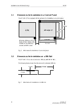
The CP 243-1 IT is equipped with bored holes for installation in a control panel.
CP 243-1 IT
63.2 mm
71.2 mm
96 mm
88 mm
80 mm
Minimum distance of 9.5 mm
between the modules when
installed in the switching
cabinet wirh M4 screws
CPU
Fig. 6 Dimensions for installation in a control panel
3.2
Dimensions for Installation on a DIN Rail
The CP 243-1 IT can be mounted on a DIN rail (DIN EN 50 022).
The following figure shows the dimensions of a standard DIN rail.
35 mm
7.5 mm
1.0 mm
Fig. 7 Dimensions for installation on a DIN rail
Содержание CP 243-1 IT
Страница 46: ...Installation and Commissioning 03 03 CP 243 1 IT J31069 D0429 U001 A0 7618 46 ...
Страница 94: ...Programming 03 03 CP 243 1 IT J31069 D0429 U001 A0 7618 94 ...
Страница 106: ...Diagnosis 03 03 CP 243 1 IT J31069 D0429 U001 A0 7618 106 ...
Страница 120: ...Technical Data 03 03 CP 243 1 IT J31069 D0429 U001 A0 7618 120 ...
Страница 130: ...Example 03 03 CP 243 1 IT J31069 D0429 U001 A0 7618 130 ...

