03/03
Example
CP 243-1 IT
J31069-D0429-U001-A0-7618
123
Appendix B Example
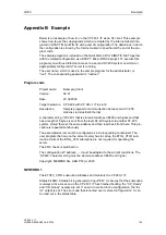
Below is an example of how to run the CP 243-1 IT as an S7 client. This example
shows how to use the subprograms which are created by the Internet wizard inte-
grated in STEP 7 Micro/WIN 32 at the end of configuration. The data block in which
the configuration is stored by the Internet wizard is specified at the end of the pro-
gram code.
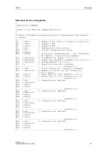
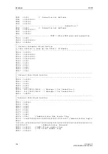
The sample program is included on the QuickStart-CD for SIMATIC NET together
with the related configuration as a STEP 7 Micro/WIN 32 project. To execute this
program you will need Ethernet access to a second S7-200 system on which an
appropriately configured S7 server is running.
The user name, which is used in the sample program for the administrator, is
“root”. The corresponding password is “rootroot”.
Program code
Project name:
Example_Client
Version:
02.01
Date 20.02.2003
Target hardware: CPU 224 with CP 243-1 IT in slot 0
Description:
Sample program for communication between two S7-200
stations via Industrial Ethernet
A character string (“CP243”) that is stored at address VB500 and higher and that
has a length of 5 bytes is sent from the local S7-200 system to another S7-200
system, stored there at the same address and then read back from there. This pro-
cedure is repeated continuously.
The associated server must be configured as a corresponding counterpart. The
user program that runs on the server merely has to call up the ETHx_CTLR sub-
routine. Calls of the ETHx_XFR subroutine are not required for operating the
server.
The CRC check is switched on.
The configuration (IP address, …) must be adapted to the current conditions. The
“CP243” character string must be stored at address VB500 and higher.
Copyright: SIEMENS AG, A&D PT2 (c) 2003
NETWORK 1
The ETHT0_CTRL subroutine initializes and monitors the CP 243-1 IT.
Status bit SM0.0 status bit is generated at input "EN". It ensures that the subroutine
is always active. As soon as the CP 243-1 IT has finished booting, the “CP_Ready”
and “CH_Ready” outputs are set. If an error occurred in the configuration, the “Er-
ror” output is set. The error code that is carried over is stored in flag word 2. It can
be read out in the status table.
Содержание CP 243-1 IT
Страница 46: ...Installation and Commissioning 03 03 CP 243 1 IT J31069 D0429 U001 A0 7618 46 ...
Страница 94: ...Programming 03 03 CP 243 1 IT J31069 D0429 U001 A0 7618 94 ...
Страница 106: ...Diagnosis 03 03 CP 243 1 IT J31069 D0429 U001 A0 7618 106 ...
Страница 120: ...Technical Data 03 03 CP 243 1 IT J31069 D0429 U001 A0 7618 120 ...
Страница 130: ...Example 03 03 CP 243 1 IT J31069 D0429 U001 A0 7618 130 ...


