Configuration
03/03
CP 243-1 IT
J31069-D0429-U001-A0-7618
70
4.4.2
Structure of Configuration Data Block (CDB)
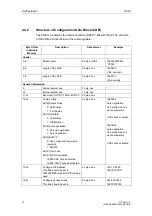
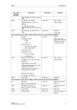
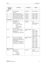
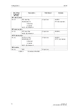
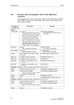
The CDB is created by the Internet wizard in STEP 7 Micro/WIN 32. The structure
of the CDB is shown below in the following table.
Byte Offset
in Variable
Memory
Description
Data Format
Example
Header
0-4
Module name
5 bytes, ASCII
16#4350323433
“CP243”
5-6
Length of the CDB
2 bytes, hex
16#006C
(108, decimal)
7-8
Length of the NPB
2 bytes, hex
16#0014
(20, decimal)
General information
9
Internal system use
1 byte, hex
10
Internal system use
1 byte, hex
11-12
Reserved for STEP 7 Micro/WIN 32
2 bytes, hex
13-14 Common
flag
Bit [0] Duplex mode
0:
Half
duplex
1: Full Duplex
Bit [1] Data rate
0: 10 Mbit/sec
1: 100 Mbit/sec
Bit [2] Auto negotiation
0: No auto negotiation
1:
Auto
negotiation
Bit [3] BOOTP
0: Use configured network pa-
rameters
1:
BOOTP
Bit [4-7] Not used
Bit [8-15] CRC validation
16#00 CRC check activated
16#AC CRC check deactivated
2 bytes, hex
16#0004:
Auto negotiation
Use configured net-
work parameters
CRC check activated
16#AC04:
Auto negotiation
Use configured net-
work parameters
CRC check activated
15-18
Configured IP address
This field should be set to
16#00000000 when BOOTP is being
used.
4 bytes, hex
192.12.45.23:
16#C00C2D17
19-22
Configured subnet mask
This field should be set to
4 bytes, hex
255.255.255.0:
16#FFFFFF00
Содержание CP 243-1 IT
Страница 46: ...Installation and Commissioning 03 03 CP 243 1 IT J31069 D0429 U001 A0 7618 46 ...
Страница 94: ...Programming 03 03 CP 243 1 IT J31069 D0429 U001 A0 7618 94 ...
Страница 106: ...Diagnosis 03 03 CP 243 1 IT J31069 D0429 U001 A0 7618 106 ...
Страница 120: ...Technical Data 03 03 CP 243 1 IT J31069 D0429 U001 A0 7618 120 ...
Страница 130: ...Example 03 03 CP 243 1 IT J31069 D0429 U001 A0 7618 130 ...

