4.1.3
Main components
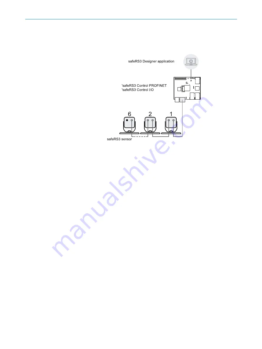
safeRS3 is composed of a control and up to six sensors. The safeRS3 Designer
application allows system operation configuration and checks.
4.1.4
Control - sensor communication
The sensors communicate with the control via CAN bus using diagnostic mechanisms in
compliance with standard EN 50325-5 to guarantee SIL 2 and PL d.
For correct functioning, each sensor must be assigned an identification number (Node
ID).
Sensors on the same bus must have different Node IDs. By default, the sensor does not
have a pre-assigned Node ID.
4.1.5
Control - machinery communication
The controls communicate with the machinery via I/O (see
and
).
safeRS3 Control PROFINET is provided with a safety communication on a Fieldbus
interface. The Fieldbus interface allows safeRS3 Control PROFINET to communicate in
real-time with the PLC of the machinery in order to do the following:
l
send information about the system to the PLC (e.g. the position of the detected
target)
l
receive information from the PLC (e.g. to change the configuration dynamically)
For details, see
Fieldbus communication on page 30
.
safeRS3 Control PROFINET is provided with an Ethernet port that allows an unsafe
communication on a Modbus interface (see
Modbus communication on page 32
).
4.1.6
Applications
safeRS3 integrates with the machinery control system: when performing safety
functions or detecting failures, safeRS3 deactivates the safety outputs and keeps them
4 GET TO KNOW SAFERS3
8027489/2022-03-01 | SICK
Subject to change without notice
O P E R A T I N G I N S T R U C T I O N S | safeRS3
19


