6
COMMISSIONING
88
8020776/12AX / 2019-05-31|SICK
O P E R A T I N G I N S T R U C T I O N S | Free Flow Profiler
Subject to change without notice
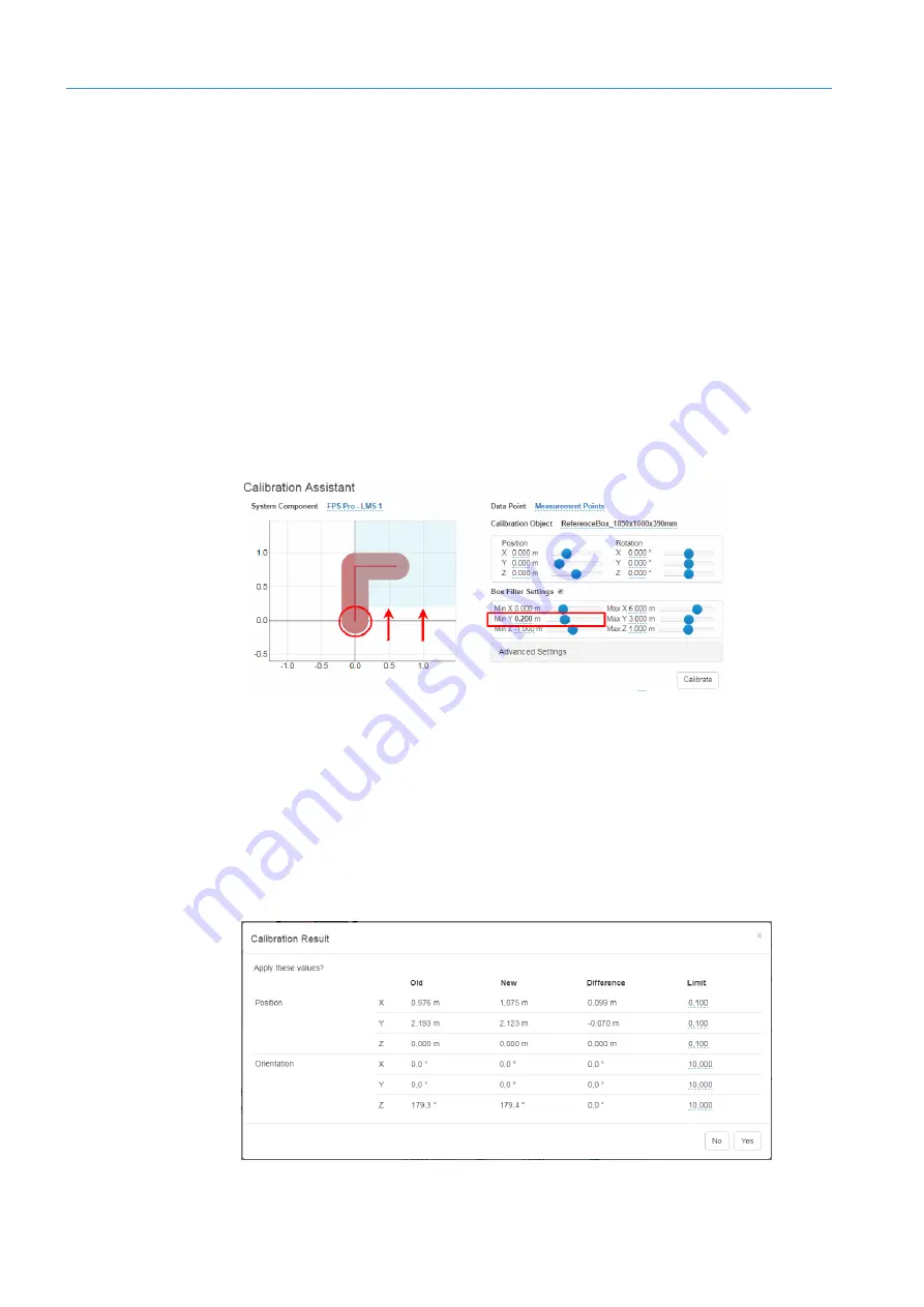
The continuous red line represents the contour of the reference object. Meanwhile, the
dotted red line indicates the current positions of the measurement points. The
measurement points do not yet coincide exactly with the line of the reference object. The
discrepancy is corrected by carrying out calibration.
The light-red area defines the calibration range within which the measurement points are
processed and optimized so that they end up coinciding exactly with the reference line of
the object.
The blue rectangle represents the box filter. This defines a kind of prefilter for determining
which measurement points should be included in the calibration process.
Box filter settings
To prevent the points on the ground from being included in the calibration process and
distorting the results, you have to blank them out.
▸
To do this, drag the blue area up by approximately 20 cm. You can either enter the
value directly in the
Min Y
field or you can use the slide control instead.
The points on the ground within the red calibration area (red circle) will now be ignored
during calibration.
Starting calibration
▸
Click the
Calibrate
button.
The measurement points are optimized during the calibration process and moved onto
the red contour line of the reference object.
The calibration result is displayed in a separate window. This shows the previous and
corrected position values as well as the difference between them.


