


AR-BC260 SETTING AND ADJUSTMENTS 8 - 8
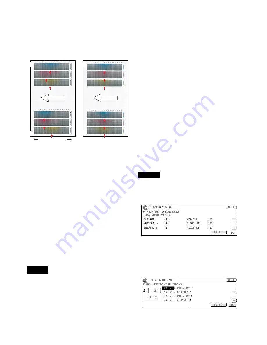
10) Check the printed image skew (distortion) pattern.
Compare the same color print pattern on the front frame side
with that on the rear frame side, and check that the difference
between the two highest-density areas is within 2 steps.
(Compare the same color print pattern on the front frame side
with that on the rear frame side. There is no need for the posi-
tions of the highest-density areas of the print color patterns of
all the colors to be aligned on a line. Compare only the same
color pattern positions.)
If the above conditions are not satisfied, remove the developing
unit on the left and turn the print engine image skew adjustment
screw on the front frame side.
To adjust the print engine image skew of Cyan, for example,
remove the Magenta developing unit. (To adjust the print engine
image skew of Yellow, however, this is not required.)
At that time, use SIM 7-1 to set DV CHECK DISABLE to Enable
and to disable the developing unit installation detection.
When the image pattern on the front frame side is skewed to the
right (arrow direction A) with the rear frame side as the reference,
turn the adjustment screw clockwise. When the image pattern is
skewed to the left (arrow direction B), turn the adjustment screw
counterclockwise.
When the adjustment screw is turned 1/4 rotation, the image posi-
tion is shifted by one dot.
Remark: The print engine image focus adjustment is performed
by changing the distance between the LED array unit
and the OPC drum.
The print engine image skew adjustment is performed
by changing the parallelism of the LED array unit for the
OPC drum.
If either of the two adjustments is performed, it may
affect the other adjustment due to the machine structure.
After completion of the above procedures, check that
both of the above two adjustments are satisfied.
There are two methods of the image registration adjustment: the
manual adjustment and the automatic adjustment. Either of them
uses the simulation.
This adjustment is required in the following cases:
• When the scanner (writing) unit is replaced.
• When the scanner (writing) unit is removed from the machine.
• When color image mis-resist is generated in the main scanning
direction.
• When color image mis-resist is generated in the sub scanning
direction.
• When installation or the installing place is changed.
• When maintenance is performed. (When the OPC drum, the
photoconductor cartridge, the transfer unit, or the transfer belt is
replaced.)
• When U2 trouble occurs.
• When ICU PWB is replaced.
• When EEPROM on ICU PWB is replaced.
Remark: Though SIM 50-22 is not performed under the following
conditions, the image registration adjustment is per-
formed automatically.
∗
When the toner cartridge is replaced.
∗
At every 8,000 copies (total of print quantity and copy quantity)
(When 8,000 copies is reached during a job, the machine stops
after completion of the job.)
If the set item AR of SIM 44-1 is set to OFF (Disable), the above
operation is not performed.
After setting the image registration to the best by SIM 50-20, when
the image registration adjustment is automatically performed, the
best-adjusted condition may be varied. To avoid this, set the item
AR of SIM 44-1 to OFF (Disable).
Note:
Before executing this adjustment, check that the following adjust-
ments have been properly completed.
∗
Print engine image focus adjustment (Scanner (writing) unit)
∗
Print engine image skew adjustment (Scanner (writing) unit)
∗
Image registration sensor adjustment
∗
SIM 48-6 FSM (Fuser roller speed) is set to the default.
Default setup of SIM 48-6 FSM (Fuser roller speed)
D: 80 (For paper of 420mm or shorter in the transport direction)
I: 85 (For paper of 420mm or longer in the transport direction)
J: 85
K: 70
This adjustment is used to perform the image registration adjust-
ment in the main scanning direction and in the sub scanning direc-
tion at the same time with the simulation.
1) Enter the SIM 50-22 mode.
SIM 50-22
2) Press the [EXECUTE] key.
The [EXECUTE] key is highlighted, and the image registration
automatic adjustment is started. After completion of the adjust-
ment, the [EXECUTE] key returns to the normal display.
The adjustment process status is indicated with (
∗
) mark. It
takes several minutes to complete the adjustment.
3) Enter the SIM 50-20 mode.
SIM 50-20
4) Select the A4 (11 x 8 1/2) size paper feed tray.
5) Press the [EXECUTE] key.
The image registration adjustment pattern is printed.
ADJ 4
Image registration adjustment
B
A
Improper adjustment
Proper adjustment
Rear
side
Paper exit side
Front
side
Rear
side
Front
side
Paper exit side
ADJ 4A
Image registration adjustment
(Auto adjustment)


