12
MOVILINK
®
device profile
Coding of the process data
Manual – PROFINET IO Interfaces, Field Distributors
144
12.1.3
Process output data
Process output data is sent from the higher-level controller to the MOVIMOT
®
inverter
(control information and setpoints). They only take effect in the MOVIMOT
®
inverter if
the RS485 address in the MOVIMOT
®
inverter (DIP switches S1/1 to S1/4) is set to a
value other than "0".
The MOVIMOT
®
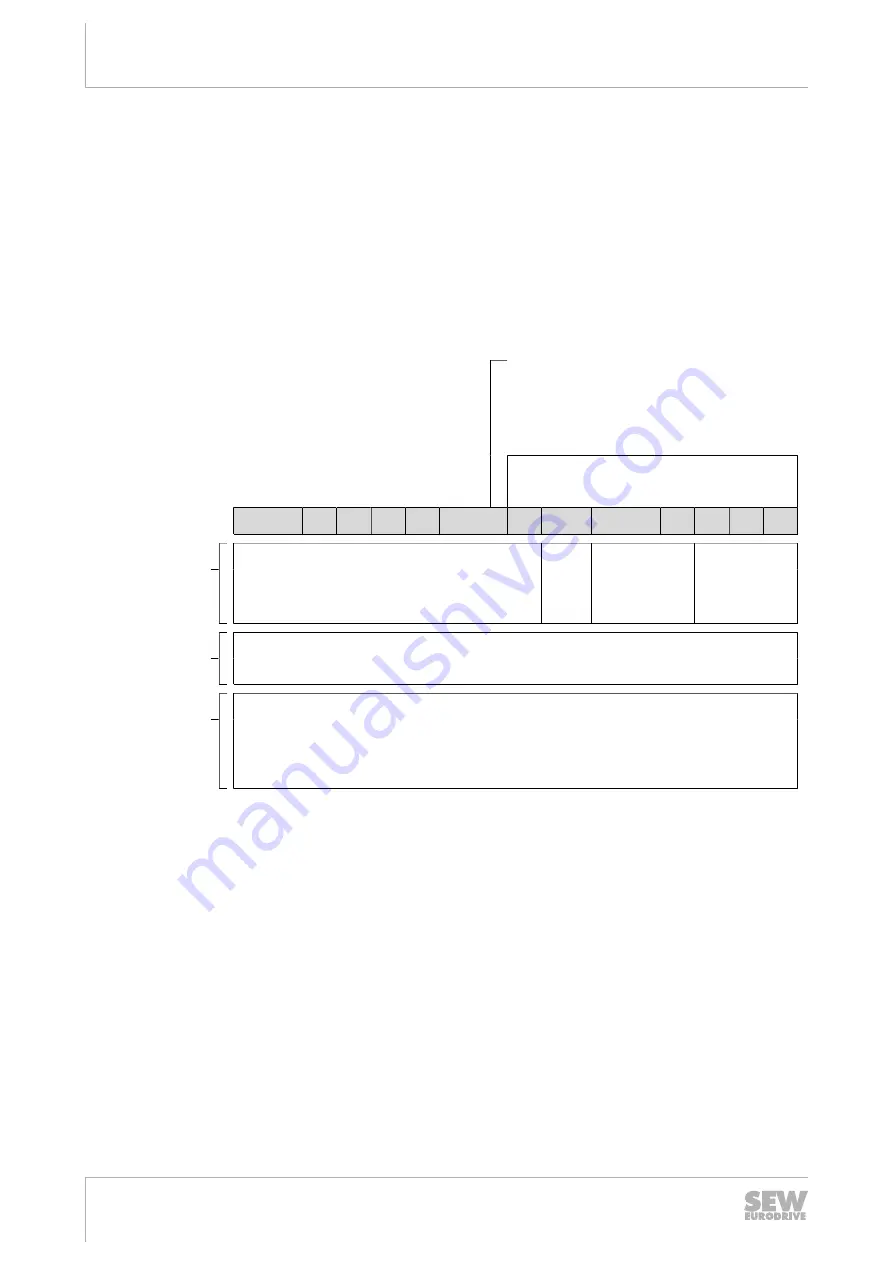
drive can be controlled via the following process output data:
•
PO1: Control word
•
PO2: Speed [%] (setpoint)
•
PO3: Ramp
Virtual terminals for releasing the brake
without drive enable,
only when MOVIMOT
®
switch S2/2 = “ON”
(adhere to MOVIMOT
®
operating instruc-
tions)
Basic control block
15
14
13
12
11
10
9
8
7
6
5
4
3
2
1
0
PO1: Control
word
Reserved for special functions = "0"
"1" =
Reset
Reserved =
"0"
"1 1 0" = en-
able
otherwise
stop
PO2: Setpoint
Signed percentage value / 0.0061%
Example:
-80% / 0.0061% = -13115 = CCC5
hex
PO3: Ramp
(for
3-word protocol
only)
Time from 0 to 50 Hz in ms (range: 100 – 10000 ms)
Example:
2.0 s = 2000 ms = 07D0
hex
Control word bit 0 – 2
The "Enable" control command is set with bits 0 – 2 by entering the control word =
0006
hex
. The CW and/or CCW input terminal must also be set to +24 V (jumpered) to
enable the MOVIMOT
®
drive.
The "Stop" control command is issued by resetting bit 2 = "0." Use the stop command
0002
hex
to enable compatibility with other SEW‑EURODRIVE inverter series.
MOVIMOT
®
inverter always triggers a stop with the current ramp whenever bit 2 = "0,"
regardless of the status of bit 0 and bit 1.
Control word, bit 6 = reset
In the event of a malfunction, the fault can be acknowledged by setting bit 6 = "1" (Re-
set). For reasons of compatibility, any control bits not assigned must be set to the
value "0".
22870857/EN – 12/2016


