background image

3

Application

Control and visualization

Assembly and Operating Instructions – Parallel Arm Kinematics Kit

18

3.5

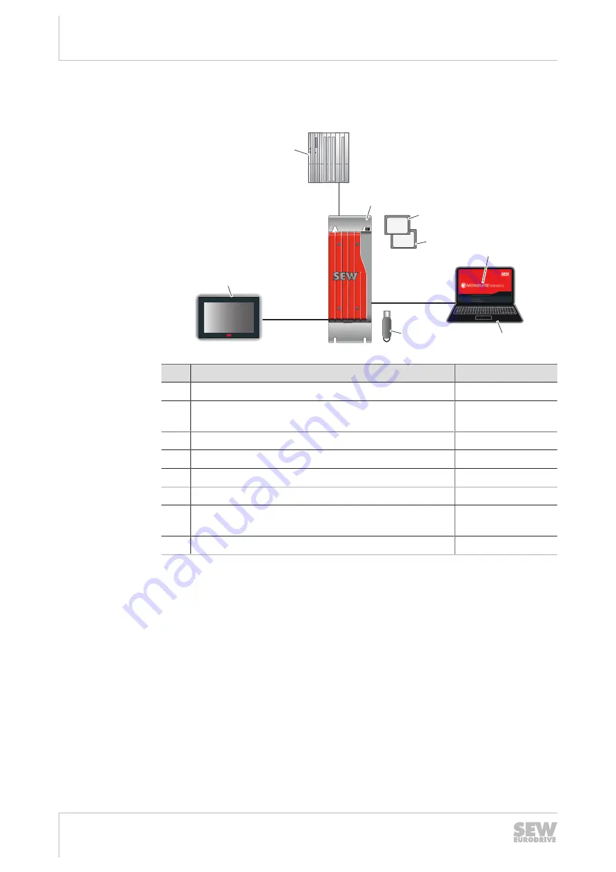
Control and visualization

3.5.1

Technical diagram

[1]

[2]

[7]

[8]

[4]

[3]

[5]

[6]

20451967883

No.

Component

Part number

[1]

Higher-level controller (PLC) (optional)

[2]

MOVI‑C

®

 CONTROLLER power UHX85A-R

(PROFINET) control cabinet controller

Configured

[3]

Windows memory card OMW72A (optional)

28208331

[4]

CFast memory card OMH85A

Configured

[5]

Software

[6]

Laptop

[7]

Runtime Licence Dongle ORV71C. USB-Dongle for
HMI-Builder PRO (optional)

17974305

[8]

Monitor (optional)

Configurable

3.5.2

Functional principle

The  MOVI-C

®

  CONTROLLER  power  control  cabinet  controller  coordinates  the  axes

and thus the movements of the robot.

The data of the application is visualized on a monitor.

Components

The used components depend on the design of the robot:

Stand-alone: A MOVI-C

®

 CONTROLLER power control cabinet controller controls

several MOVIDRIVE

®

 system drive inverters.

Integrated:  A  MOVI-C

®

  CONTROLLER  power  control  cabinet  controller  controls

one or several MOVIDRIVE

®

 modular application inverters.

The control cabinet controller can control up to 32 interpolating axes and 32 auxiliary
axes.  The  parameterization  and  startup  of  the  devices  are  performed  in  the
MOVISUITE

®

 software.

25797530/EN – 04/2018

Содержание MAXOLUTION MAXO-RPS-.-R Series

Страница 1: ...97530_0418 Drive Technology Drive Automation System Integration Services Assembly and Operating Instructions MAXOLUTION Production Robot Parallel Arm Kinematics Kit MAXO RPS R Edition 04 2018 25797530...

Страница 2: ...SEW EURODRIVE Driving the world...

Страница 3: ...8 Setup and installation 10 2 9 Electrical installation 10 2 10 Protective separation 11 2 11 Startup and operation 11 2 12 Inspection and maintenance 12 3 Application 13 3 1 Description 13 3 2 Type d...

Страница 4: ...ctions Parallel Arm Kinematics Kit 4 6 2 Operating modes 52 7 Service 53 7 1 Electronics service from SEW EURODRIVE 53 7 2 Waste disposal 53 8 Inspection and maintenance 54 9 Technical data 55 10 MAXO...

Страница 5: ...e following table shows the grading and meaning of the signal words for safety notes Signal word Meaning Consequences if disregarded DANGER Imminent hazard Severe or fatal injuries WARNING Possible da...

Страница 6: ...aim under limited warranty Read the information in this documentation This is essential for fault free operation and fulfillment of any rights to claim under limited warranty Read the documentation be...

Страница 7: ...n also order prin ted and bound copies of the documentation from SEW EURODRIVE 1 5 Product names and trademarks The brands and product names in this documentation are trademarks or registered trademar...

Страница 8: ...on devices 2 3 Target group Planning and design Any work related to planning and design which is necessary for the correct integration of the drive solution into the machine system may only be perform...

Страница 9: ...persons who are trained appropriately The purpose of the instruction is that the persons are capable of performing the required tasks and work steps in a safe and correct manner 2 4 Designated use The...

Страница 10: ...you receive the delivery Inform the ship ping company immediately about any damage If the product is damaged it must not be assembled installed or started up Observe the following notes when transpor...

Страница 11: ...y im mediately in the event of transportation damage Do not start up damaged products Monitoring and protection devices Do not deactivate monitoring and protection devices even for a test run Switch o...

Страница 12: ...are no longer illuminated does not indicate that the device has been disconnected from the power supply and no longer carries any voltage Automatic restart Faulty mechanical blocking or internal safe...

Страница 13: ...are The robot arms and drives are mounted in a base frame The joint axes are driven by motors enabling the arms to move The arms can reach very high speeds and dynam ics The tool mounted to the arms e...

Страница 14: ...he drive technology Free programming of three dimensional movement Visualization on a monitor Automatic mode manual mode and jog mode Configuration with teach mode 3 2 Type designation The type design...

Страница 15: ...atics 2 arms 2 3 axes 1 1 1 2 2 20413212555 1 Axis 2 Arm Tripod kinematics 3 arms 3 5 axes 1 1 1 1 2 2 2 20413216523 3 3 2 Movement dimensions Axes Work envelope 2 1 optional axis XZ level optional in...

Страница 16: ...oading 4 Height difference between loading and unloading position 5 Path length In addition the following data is important Robot type 2 arms or 3 arms Duration of loading and unloading of the product...

Страница 17: ...city Cycles per minute 2 Optional 1000 342 mm 30 kg 50 1500 347 mm 35 kg 45 3 Optional 800 250 mm 3 kg 200 1100 250 mm 3 kg 180 1300 250 mm 3 kg 150 1600 350 mm 12 kg 100 3 Default Default 800 250 mm...

Страница 18: ...or optional Configurable 3 5 2 Functional principle The MOVI C CONTROLLER power control cabinet controller coordinates the axes and thus the movements of the robot The data of the application is visua...

Страница 19: ...o grammed as required with programming languages according to standard IEC 61131 3 The Windows memory card OMW72B extends the control cabinet controller by a Win dows platform and can be used for plan...

Страница 20: ...20363369739 No Component Part number 1 MOVI C CONTROLLER power control cabinet controller Configured 2 Line filter NF0120 503 17984270 3 MOVIDRIVE MDX90A 0070 5E3 4 S00 drive inverter with braking res...

Страница 21: ...number 1 MOVI C CONTROLLER power control cabinet controller Configured 2 Line filter NF0420 513 17983789 3 Power supply module MDP90A 0100 503 4 C00 op tional with braking resistor Configured 4 MOVID...

Страница 22: ...o Component Part number 1 MOVI C CONTROLLER power control cabinet controller Configured 2 Line filter NF0120 503 17984270 3 MOVIDRIVE MDX90A 0070 5E3 4 S00 drive inverter with braking resistor BW047 0...

Страница 23: ...number 1 MOVI C CONTROLLER power control cabinet controller Configured 2 Line filter NF0420 513 17983789 3 Power supply module MDP90A 0100 503 4 C00 op tional with braking resistor Configured 4 MOVID...

Страница 24: ...motion a drive for tilting of the tool is provided for 4 axis vari ants Stand alone The drives of the tools are controlled by MOVIDRIVE system inverters 3 1 4 5 2 20367461643 No Component Part number...

Страница 25: ...cable 4 pole Length 0 75 m 18167039 3 Servo motor cable with SM11 M23 connector for a fixed installation Length configurable 05904544 Encoder cable Length configurable 13324535 4 Synchronous servomot...

Страница 26: ...g the work Disconnect Secure the device against a restart Check that no voltage is applied Ground and short cir cuit it Cover or cordon off neighboring live parts 4 2 Mechanical installation 4 2 1 Cle...

Страница 27: ...y using cover plates The installation may only be carried out by trained specialists Drive Observe the following rules The specifications on the nameplate of the drive must correspond to the supply sy...

Страница 28: ...ricated cables listed in the documentation When using devices with integrated safety func tions according to EN ISO 13849 you also have to adhere to all the conditions and re quirements for the instal...

Страница 29: ...connector housing is applied on both ends over a wide area For cables with double shielding e g hybrid cables the outer shielding is applied to the unit side and the inner shielding to the other side...

Страница 30: ...mbly and installation Procedure Assembly and Operating Instructions Parallel Arm Kinematics Kit 30 4 5 Procedure Install the hardware as described in the documentation for the components 25797530 EN 0...

Страница 31: ...es are connected correctly Observe the connection instructions in the component documentation 5 2 MOVIKIT Robotics MOVIKIT Robotics 5 2 1 Operating principle Process controller The MOVIKIT Robotics is...

Страница 32: ...ocumentation Drives robot arms Drive tool gripper CMP40 CMP112 CMPZ71 CMPZ100 Synchron ous Servomotors operating instructions Section Startup MOVIDRIVE drive inverters Stand alone MOVIDRIVE system app...

Страница 33: ...1 Dismount all secondary arms 2 2 2 1 1 1 21362190731 1 Primary arms 2 Secondary arms 2 Release the brakes of the motors for the primary arms 3 Turn the primary arms downwards in order to mount the re...

Страница 34: ...of the required arm in manual mode 7 Push the upper arm with its ball joint against the referencing tool 2 1 21373602699 1 Referencing tool 2 Primary arm 8 Apply the motor brake to the arm 9 Referenc...

Страница 35: ...ical damage The alignment of the inclination axis depends on the position of the internal gear unit The gear unit can have 2 positions with mounted referencing tool rotated by 180 from each other The...

Страница 36: ...p nut 4 Tighten the star grip nut until the referencing tool has been fixed 5 Open the MOVISUITE software and release the motor brake of the rotary and in clination axis in manual mode 6 Push the arm...

Страница 37: ...er is supplied with voltage and started The controller is connected to the engineering PC and can be scanned in MOVISUITE 5 5 2 Sequence Startup procedure 1 Create MOVISUITE project 2 Add axes 3 Confi...

Страница 38: ...Configure the MultiMotion axis see MOVIKIT MultiMotion documentation 3 Save your settings 5 5 6 Creating IEC editor project 1 Go to the Startup work phase 2 Perform a network scan Connect the control...

Страница 39: ...ory Other 4 Select SEW_MOVIKIT_Robotics 5 If required select further libraries 6 Confirm your entries Importing open program code 1 Mark the node Application in the device tree 20615135883 2 Select th...

Страница 40: ...2 Enter the name TaskLowPriority and click add 3 Enter the value 31 in the edit box 4 Select the value Cyclic in the drop down list Type 5 Enter the value t 20ms in the edit box Interval 6 Insert the...

Страница 41: ...uired libraries see chapter Integrating the library 2 39 2 Double click GVL_System_Robot under Application MOVIKIT Robotics in the device tree 3 Instantiate the proper kinematic model Selecting the co...

Страница 42: ...tification window 3 Compile the project F11 button 4 Correct all errors of the compilation see notification window 5 Login to the controller button Alt F8 6 Start the controller F5 button 5 6 Robot pr...

Страница 43: ...he robot its pose and the travelled path 9 Program status 10 Access switching 11 Selection of the robot instance 5 6 2 Making the connection to the PLC 1 Select the IP address Standard IP address of t...

Страница 44: ...ram 4 If END_PROG is included mark the line and click the Delete button 5 Insert the selection of a motion parameter set Select the value SEL_MOTION SET in the drop down list New Block Click the Add b...

Страница 45: ...essage Done occurs the saving was successful 5 6 4 Motion commands Motion commands are commands to move to a position Linear segments To move to a final pose on a straight line with prior blending wit...

Страница 46: ...ssignment 3 Setting if a fixed value VAL or the value of a variable VAR is to be assigned 4 If 3 is set to VAL Value that is assigned If 3 is set to VAR Index of the real variable whose value is assig...

Страница 47: ...of the IF condition Bool variable 2 Drop down list to replace 1 3 Line with the IF condition start 4 Lines to be executed if 1 is fulfilled 5 Line with the IF condition end 5 Move the start and end of...

Страница 48: ...condition The condition can be a bool variable or a status signal e g end of motion MO TION_DONE Waiting for adding bool variable 1 Mark the line under which you want to insert the waiting for bool v...

Страница 49: ...with name and value of the bool variable These variables can be written and read by the IEC and the robot program REALVAR i Variables with name and value of the floating point variable These variable...

Страница 50: ...rror Correct the error status by increasing the edge of signal error reset Setpoints active For controlling the robot Setpoints Active TRUE must be set If not determine the cause 1 Check if there is a...

Страница 51: ...ram for the process controller SEW EURODRIVE is not liable for the content of the sample program 5 7 6 Handling errors You can detect whether the MOVIKIT Robotics has an error status from the signal e...

Страница 52: ...eakage of parts during operation Damage to property Adhere to the technical specifications 6 2 Operating modes Automatic mode A parameterized program is automatically executed in automatic mode Manual...

Страница 53: ...n of the application application control via terminals or serial Connected motor motor voltage star or delta connection Error message on the status display Nature of the fault Accompanying circumstanc...

Страница 54: ...tive and faulty components of the electric system immediately Do not operate the system with defective components After modifications of the system perform an electrical inspection CAUTION Risk of bur...

Страница 55: ...9 Technical data Assembly and Operating Instructions Parallel Arm Kinematics Kit 55 9 Technical data Note the technical data in the documentation for the components 25797530 EN 04 2018...

Страница 56: ...cn France Hagenau SEW USOCOME 48 54 route de Soufflenheim B P 20185 67506 Haguenau Cedex Tel 33 3 88 73 67 00 Fax 33 3 88 73 66 00 http www usocome com sew usocome com India Chennai SEW EURODRIVE Indi...

Страница 57: ...nejsv gen 6 8 553 03 J nk ping Box 3100 S 550 03 J nk ping Tel 46 36 34 42 00 Fax 46 36 34 42 80 http www sew eurodrive se jonkoping sew se USA Lyman SEW EURODRIVE INC 1295 Old Spartanburg Highway P O...

Страница 58: ......

Страница 59: ......

Страница 60: ...SEW EURODRIVE Driving the world SEW EURODRIVE GmbH Co KG Ernst Blickle Str 42 76646 BRUCHSAL GERMANY Tel 49 7251 75 0 Fax 49 7251 75 1970 sew sew eurodrive com www sew eurodrive com...

Отзывы: