SEA SYSTEMS
INSTALLATION AND USE
STK3-GMV10 Control panel and Pre-wiring
For Hydraulic Elevators
MSTK3-GB
Rev.04
05/02/12
© Sea Systems S.r.l.
Page 13 of 81
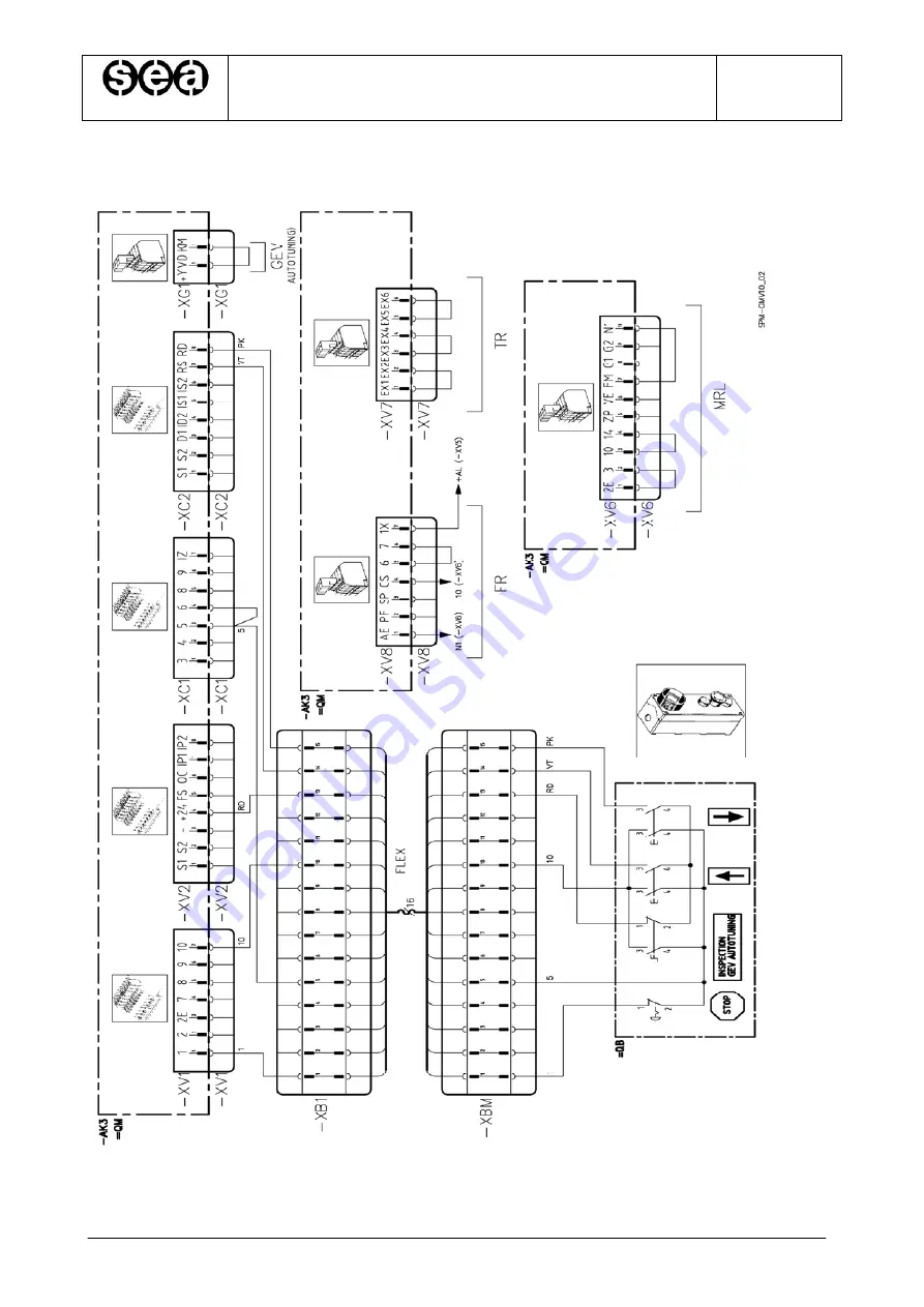
Dia. B.6.2 Connections for Pre-installation Operations Schematic Diagram
Страница 1: ...r Elevators Via San Carlo 13 20010 Bareggio Milan ITALY Tel 39 02 90 36 34 99 Fax 39 02 90 36 35 00 Internet www seasystems it e mail sea seasystems it MSTK3 GB Rev 04 05 02 12 MANUAL FOR INSTALLATION AND USE STK3 GMV10 Control panel and Pre wiring For Hydraulic Elevators ...
Страница 2: ...le to set a secret Access Code determine the conditions of elevator operation monitor what malfunctions or breakdowns occurred and how many times they occurred control the operation of the elevator and its doors and modify the functional characteristics of the elevator Many specific functions for a particular system can be programmed without having to modify the cabling of the Control panel The fu...
Страница 3: ... 29 B 10 ISOLATION TEST 30 B 11 TESTS FOR AMENDMENT A3 OF EN81 2 31 C PROGRAMMING AND DIAGNOSTICS 32 C 1 CHARACTERISTICS OF THE PT01 PROGRAMMER 32 C 2 WAIT CONNECTION AND MODE 32 C 3 PROGRAMMER PARAMETERS AND USE 33 C 4 IDENTIFICATION AND ACCESS 34 C 5 LEVEL OF ACCESS 34 C 6 PARAMETERS 35 D MAINTENANCE 67 D 1 BATTERY REPLACEMENT 67 D 2 SHAFT SENSORS 67 D 3 REPLACEMENT OF THE STK3 B BASIC ELECTRONI...
Страница 4: ...NG CONTEMPORARY SELECTIVE OPENING PHOTOCELL OPEN CLOSE DOOR BUTTON VARYING DOOR OPEN CLOSED STOP ON DIFFERENT FLOORS VARIOUS FUNCTIONS VIEW AND DELETE BREAKDOWN MALFUNCTION CODES SAFETY CONTROL PHASE SEQUENCE AND FAILURE TIMER MANAGEMENT RUN TIME LOW SPEED TIME INTERMEDIATE CONTROL 15 S HYDRAULICS MAIN FLOOR STOP ADJUSTMENT OF LEVELING SPACE EARLY DOOR OPEN RESERVED PREFERENTIAL FIREMAN FIRE OPERA...
Страница 5: ...rom 110 to 440 V AC Single and three phase Operation Voltage 48 V DC Sliding block Solenoid valve voltage 48 V DC Operators 30 V DC Three phase Arrow Out of Service Occupied signal outputs 24 V DC 12 W Max Each Arriving Reservation signal outputs 24 V DC 2 4 W Max Each Auxiliary inputs 24 V DC 10 mA Safety inputs Opto isolated EN 81 1 and EN 81 2 Compliant Operating Temperature 0 40 C Data Memory ...
Страница 6: ...nd Pre wiring For Hydraulic Elevators MSTK3 GB Rev 04 05 02 12 Sea Systems S r l Page 6 of 81 B INSTALLATION Fig B 1 General pre wiring layout with paragraphs for reference during installation SHAFT Par B 7 CAB ROOF Par B 8 CONTROL PANEL Par B 5 Par B 6 Par B 9 ...
Страница 7: ...llation diagrams This documentation must be kept by the system manager for correct and safe installation and maintenance of the elevator This documentation is considered an integral portion of the system and must not be damaged Pages must not be removed During use have care not to dirty the pages in order to preserve its legibility The terms of warrantee are indicated on the back of the product tr...
Страница 8: ... shoes Safety Belt Ear protection Safety Signs Do not wear loose clothing or objects necklaces watches ties and tie back long hair Do not keep sharp objects or objects that can puncture ex screwdrivers scissors in shirt pockets Do not tamper with spoil or hide warning signs labels If illegible request their immediate replacement To lift heavy loads use suitable equipment in order to limit spinal i...
Страница 9: ...Type of panel meters start ups correspond to what was ordered and what is listed on the order confirmation Check that all of the material needed for installation is available according to the list attached to the documents for the panel The part numbers for the materials are located on the bags that contain the parts and are called out in the installation instructions in this manual Check the stat...
Страница 10: ...a Machine Room Cabinet Fasten the two supports to the upper and lower parts of the control panel Hook the panel on the upper guide at the bottom of the cabinet Fasten the panel to the lower guide at the bottom of the cabinet c Mounting the panel on MRL systems guides Fasten the two supports on the upper and lower parts of the control panel Fasten the support plates to the system guides at a distan...
Страница 11: ...and the connection contained in kit PBU02 as shown in the schematic diagram Dia 2 6 2 4 Connect the connectors with the integrated bridges p n PBU02 according to the schematic diagram Dia 2 6 2 and based on they type of system MRL System Æ Insert Connector XV6 TR System Reduced Head Æ Insert Connector XV7 FR System Reduced Pit Æ Insert Connector XV8 Systems with GEV valve Æ Insert Connector XG1 on...
Страница 12: ...INSTALLATION AND USE STK3 GMV10 Control panel and Pre wiring For Hydraulic Elevators MSTK3 GB Rev 04 05 02 12 Sea Systems S r l Page 12 of 81 Dia B 6 1 Connections for Pre installation Operations Schematic Diagram ...
Страница 13: ...INSTALLATION AND USE STK3 GMV10 Control panel and Pre wiring For Hydraulic Elevators MSTK3 GB Rev 04 05 02 12 Sea Systems S r l Page 13 of 81 Dia B 6 2 Connections for Pre installation Operations Schematic Diagram ...
Страница 14: ... the side with most services NOTE Insert the strap p n P 00074 in the plug p n P 00075 before fastening the conduit Fig 1 3 Fasten the coil temporarily at the top of the shaft and lower it into the shaft from the top allowing it to descend along the side with the insert connectors to the control panel Fig 2 Fig 1 Fig 2 4 Connect the connectors of the upright to the operations panel according to th...
Страница 15: ...NOTE In general the equipment that requires shunt connections are Overrun Floor button panels Alarm sirens Shaft stop B 7 3 SERIES CONNECTIONS TO THE SHAFT LINE The series connections to the line see the installation schematic diagram must be performed using the orange connectors following the sequence shown in Figure 6 Pay particular attention to connect the last device of the series according to...
Страница 16: ...ations for series connections to shaft line Open 3 pole female connector sectioning blade Sectioned L1 phase cable positioned in contact without pealing Ground cable in contact without pealing Position the lower and upper parts of the connector and tighten using a wrench Assembly of a male connector with a female connector Press the conductors between the rip resistant clamps ...
Страница 17: ...e mid point of the travel distance using the plugs supplied p n P 00102 7 Fasten the flexible cables to the wedge support bracket in a position so that when the cab is at the absolute end of run the winds of the flexible cable do not touch the bottom of the shaft NOTE To eliminate the problem of excess bagginess and winding of the flexible cables in the shaft move the wedge support bracket upwards...
Страница 18: ...RS for the end floor speed change toggle contacts A monostable contact SIS for stopping and speed changes when rising A monostable contact SID for stopping and speed changes during decent Two monostable contacts SIZ1 SIZ2 for the safety circuit control B Installation 1 Mount the two bracketed shaft impulse generator kits p n PIV01 and PIV02 on the roof of the cab as shown in the schematic diagram ...
Страница 19: ...diagram Dia 2 8 3 2 and table Tab 2 8 3 1 Tab 2 8 3 1 Speed Change Distances Recommended for Traditional Shaft and Valve 3010 Cabin Speed m s KS Speed Change Distance When Rising mm KD Speed Change Distance When Descending mm 0 01 0 30 250 350 0 31 0 40 350 450 0 41 0 50 450 550 0 51 0 60 600 700 0 61 0 70 800 900 0 71 0 80 1000 1100 7 Adjust the stop strips for intermediary floors so that the flo...
Страница 20: ...STEMS INSTALLATION AND USE STK3 GMV10 Control panel and Pre wiring For Hydraulic Elevators MSTK3 GB Rev 04 05 02 12 Sea Systems S r l Page 20 of 81 Dia B 8 3 2 Magnet Set Up Overview for Shaft without Encoder ...
Страница 21: ...table contact SIZ for the control of the second safety circuit channel it uses the same magnet as the SIM sensor Incremental encoder installed on the roof of the cab for speed change control electronic valve speed measurement floor stop and doors open closed detection The floor area understood to be the space above and below the floor where it is possible to perform detection with the doors open i...
Страница 22: ... the distances from the end floors indicated in table Tab 2 8 4 1 shown below 6 Position the magnetic strips correctly straddling each floor as shown in the schematic diagram Dia 2 8 4 2 the diagram refers to a shaft with normal story heights or 30 cm NOTE It is necessary that they are positioned correctly straddling the floor Errors of a few cm can be corrected by manual adjustments however the r...
Страница 23: ...YSTEMS INSTALLATION AND USE STK3 GMV10 Control panel and Pre wiring For Hydraulic Elevators MSTK3 GB Rev 04 05 02 12 Sea Systems S r l Page 23 of 81 Dia B 8 4 2 Magnet Set Up Overview for Shaft with Encoder ...
Страница 24: ...st lowest floor 1 Run up to highest floor 2 Run down to lowest floor ERR0 alarms in plant ERR1 invalid shaft signal status for RS RD and IM RD 0 RS 0 IM 0 at lowest floor ERR2 encoder count between two minor 50 mm strips ERR3 No programmed stops different from No magnetic strips counted also considering the programmed reduced floors ERR4 Magnetic strips count when rising differs from count when de...
Страница 25: ...the type of error anomaly found will be indicated 9 Pres ESC to end the shaft reading and exit the menu 1 Shaft Self tuning Complete Operation finished correctly Press ESC to exit NOTE During this maneuver all of the quotas relative the magnetic strips of the floors are recorded The threshold of the floor is set to half of the distance of the measurement of the relative magnetic strip Furthermore ...
Страница 26: ...Floor Threshold 3 If misalignments persist between decent and rise runs adjust the value of the rise decent stop space on menus 3 3 3 and 3 3 4 4 At the end of the operation record the values using Menu 5 Save Data NOTE If for any reason the timing device magnets or magnetic strips are moved the Shaft Self Tuning must be repeated Tab 2 8 4 1 Speed Change Distances Recommended for Shaft with Encode...
Страница 27: ... m Parameter 3 3 5 1 and Parameter 3 3 5 2 Speed Change Space for Rise and Decent mm KRS KRD Rise and Decent Timing Device Magnet Distance mm 0 20 0 58 290 390 0 25 0 66 320 420 0 30 0 73 360 460 0 35 0 80 400 500 0 40 0 88 440 540 0 45 1 20 580 680 0 50 1 30 620 720 0 55 1 40 670 770 0 60 1 73 840 940 0 65 1 85 900 1000 0 70 1 96 960 1060 0 75 2 40 1200 1300 0 80 2 52 1260 1360 0 85 2 65 1320 142...
Страница 28: ... 4 1 1 Service Operation Mode Installation In this case commutate the shunt on the installation button panel close the oil shutter bridge XG1 XG2 and execute the command in menu 4 3 2 Service Calibration GEV Self Tuning 4 1 1 Service Operation Mode Normal In this case make certain that the safeties are closed close the oil shutter bridge XG1 XG2 and execute the command in menu 4 3 2 Service Calibr...
Страница 29: ...er line L1 L2 L3 the pump motor MC the solenoid valves YD YL YP YE and the temperature and pressure sensors RT STO SPO1 SPO2 SPO4 to the control panel as shown in the installation schematic diagram NOTE The items called out in point 3 should have already been connected during the pre installation phase as indicated in Paragraph 2 6 Connections for Pre Installation Operations 4 Turn on the panel an...
Страница 30: ...nsulate the earth wire from the power supply device AL01 4 Disconnect the pressure transducer 5 Disconnect the telephone line to the dialer FROM TO Engine Power Motors R S T U V W U1 V1 W1 U2 V2 W2 Safeties 1 10 Cabin lights L1 L N Continuous door motor OP02 OP03 OP05 OP06 OP07 OP08 Indicators OC FS Ground U U U U U Engine Power Motors R S T U V W U1 V1 W1 U2 V2 W2 NO U U U U Safeties 1 10 U NO U ...
Страница 31: ...ations between 2 and 7 operation 3 with the parameter 4 2 6 for upwards B 11 2 INSTRUCTION TO CHECK THE SELF MONITORING OF HYDRAULIC VALVES NORMALLY OPERATING NOTE The Control panel STK3 monitors the two valves once a day after the automatic dispatch to the lowest floor The operation checks separately each valve is closed If during the check a second re leveling occurs the valve is considered brok...
Страница 32: ...s Standard removable connection cable RJ45 direct not crossed max length 10 m Direct connection to the base board or to the Remote Button panel without power switch C 2 Wait Connection and mode When the connection is performed the background of the display illuminates and the following message is displayed Where xx x and yy y are the numbers relative to the Version and Release of the firmware inst...
Страница 33: ...Selection List Numerical ESC Ö Return the next higher level menu Annul the change and return to selection Move the cursor one position to the right Page upwards through the menu Shows the previous menu item Shows the previous element Increases the numerical value Ø Page downwards through the menu Shows the next menu item Shows the next element Decreases the numerical value ENT Activates the select...
Страница 34: ...4 05 02 12 Sea Systems S r l Page 34 of 81 C 4 Identification and Access STK3 GMV 10 Vxx x Ryy y Ã Ä Firmware installed Vxx x Version Number Ryy y Release Number STK3 GMV 10 S N xxxxxxxx Ã Ä Serial number of the base board GMV 10 STK3 GMV 10 PIN Insert Customer Code C 5 Level of Access Paragraph to be finalized ...
Страница 35: ...us of the door 1 means open means closed 4 indicates the status of door 2 means open means closed 1 3 Alarms Ã Ä Display of the currently active alarms Press ENT to access the list Each alarm is identified by a code described in the Alarm code Table 1 4 Reset Alarms Ã Ä Permanent elimination of the alarms Press ENT confirmation for elimination will be requested If after the elimination of the alar...
Страница 36: ...ostics Transducers 1 8 1 Oil Temp xx C Ã Ä Displays the current value of the oil plant temperature 1 8 2 Oil Pres xx x bar Ã Ä Displays the current value of the piston oil pressure Parameter only active if a pressure transducer is installed 1 8 3 Encoder xxxxxmm x xm s Real time view of cab position and speed This position is only valid after the timing is reset ...
Страница 37: ...the input signals IP9 IP1 0 Open Contact 1 Closed Contact HC 87654321 00000000 Ã Ä Displays the status of the input signals 8 X9 3 7 X9 4 6 HC6 5 HC5 4 HC4 3 HC3 2 HC2 1 HC1 0 Open Contact 1 Closed Contact FA1 FC1 FA2 FC2 0 0 0 0 Ã Ä Displays the status of the door limit switch input signals FA1 FC1 FA2 and FC2 0 Open Contact 1 Closed Contact CM1 CM2 FT1 FT2 0 0 0 0 Ã Ä Displays the status of the ...
Страница 38: ...CAB 1 OK XX XX XX XX Ã Ä Displays the communication status with the Cabin 1 Button Panel OK correct connection no connection The numbers XX must be communicated to the Technical Service if requested BUTTON PANEL CAB 2 OK XX XX XX XX Ã Ä Displays the communication status with the Cabin 2 Button Panel OK correct connection no connection The numbers XX must be communicated to the Technical Service if...
Страница 39: ...ts The count cannot be reset 1 10 2 Start Dec nnnn0 Ã Ä Displays the number of descent starts performed The count is updated every 10 starts The count cannot be reset 1 10 3 Read A nn Ã Ä Displays the maximum number of ascent to floor readings performed The count cannot be reset 1 10 4 Read D nn Ã Ä Displays the maximum number of descents to floor readings performed The count cannot be reset 1 10 ...
Страница 40: ...up Ã Ä Start up Direct Star Delta Soft Starter SCC 2 3 Valve 3010 Ã Ä Valve 3010 3010 2CH 3010 DLV A3 3010 A3 NGV01 NGV01 DLV A3 NGV A3 GEV GEV DLV A3 2 4 Transducer Pressures Ã Ä Sensor of pressure transducer obligatory for GEV valve pressure gauge 2 5 Type of MR Ã Ä Machine room MR with machine room MR without machine room 2 6 Shaft Head Standard Ã Ä Headroom Standard Reduced EN 81 21 2 7 Shaft ...
Страница 41: ...el and Pre wiring For Hydraulic Elevators MSTK3 GB Rev 04 05 02 12 Sea Systems S r l Page 41 of 81 Ã Ä 2 11 Universal Operation Ã Ä Operation Universal APB Simplex Descent Simplex Ascent Descent 2 12 Shaft Type Contacts Shaft informer With contacts Encoder ...
Страница 42: ...ange 0 0 3 0s 3 1 Settings Valve 3010 2CH This menu is displayed if the parameter 2 3 is set like 3010 2CH 1 Inspect speed Low Inspection operation speed Low speed High speed Ã Ä 2 Soft Stop x x s Delay time to activate and deactivate VMP valve Soft Stop range 0 0 3 0s 3 1 Settings Valve 3010 DLV A3 This menu is displayed if the parameter 2 3 is set like 3010 DLV A3 1 Inspect speed Low Inspection ...
Страница 43: ...isplayed if the parameter 2 3 is set like 3010 A3 1 Inspect speed Low Inspection operation speed Low speed High speed Ã Ä 2 Soft Stop x x s Delay time to activate and deactivate VMP valve Soft Stop range 0 0 3 0s Ã Ä 3 DLV on VMD on xx s Advance time to activate the door block valve DLV range 0 2 3 0 s Ã Ä 4 VMD off DLV off xx s Delay time to deactivate the door block valve DLV range 0 2 3 0 s ...
Страница 44: ...oft Stop range 0 0 3 0s 3 1 Settings Valve NGV DLV A3 This menu is displayed if the parameter 2 3 is set like NGV01 DLV A3 1 Soft Stop x x s Delay time to activate and deactivate VMP valve Soft Stop range 0 0 3 0s Ã Ä 2 DLV VMD Test xx s Activation Time to check the valves DLV and VMD during the monitoring according to Amendment A3 range 3 10 s 3 1 Settings Valve NGV A3 This menu is displayed if t...
Страница 45: ...eighboring floors This parameter allows the calculated speed to be modified in percentages Ã Ä 3 Lev Speed Ascent 0 xx m s Ascending leveling speed range 0 04 0 20 m s Ã Ä 4 Insp Speed Ascent 0 xx m s Ascending inspection speed range 0 2 0 63 m s Ã Ä 5 Ascent Offset Vinsp xx Ascending inspection speed during installation range 01 99 of the inspection speed 3 1 1 4 Ã Ä 6 Ascent Normal Acc Ascent Ac...
Страница 46: ...e value of the speed during the runs between neighboring floors This parameter allows the calculated speed to be modified in percentages Ã Ä 3 Descent Lev Speed 0 xx m s Descending leveling speed range 0 04 0 20 m s Ã Ä 4 Descent Insp Speed 0 xx m s Descending inspection speed range 0 2 0 63 m s Ã Ä 5 Descent Vinsp Offset xx Descending inspection speed during installation range 01 99 of the inspec...
Страница 47: ...rease if the plant tends to vibrate Ã Ä 2 Gain I x Gain I range 0 9 standard set point 0 Adjusts the response speed of the adjustment Increase if the plant is elastic decrease if it is slow Ã Ä 3 Gain S x Gain S range 0 9 standard set point 4 Adjusts the departure response speed Increase if slow starting decrease if it jerks when starting Ã Ä 4 Ratio 1 1 short Cab piston run ration and piston leng...
Страница 48: ...en neighboring floors This parameter allows the calculated speed to be modified in percentages Ã Ä 3 Lev Speed Ascent 0 xx m s Ascending leveling speed range 0 04 0 20 m s Ã Ä 4 Insp Speed Ascent 0 xx m s Ascending inspection speed range 0 2 0 63 m s Ã Ä 5 Ascent Offset Vinsp xx Ascending inspection speed during installation range 01 99 of the inspection speed 3 1 1 4 Ã Ä 6 Ascent Normal Acc Ascen...
Страница 49: ...the value of the speed during the runs between neighboring floors This parameter allows the calculated speed to be modified in percentages Ã Ä 3 Descent Lev Speed 0 xx m s Descending leveling speed range 0 04 0 20 m s Ã Ä 4 Descent Insp Speed 0 xx m s Descending inspection speed range 0 2 0 63 m s Ã Ä 5 Descent Vinsp Offset xx Descending inspection speed during installation range 01 99 of the insp...
Страница 50: ...int 0 Adjusts the response speed of the adjustment Increase if the plant is elastic decrease if it is slow Ã Ä 3 Gain S x Gain S range 0 9 standard set point 4 Adjusts the departure response speed Increase if slow starting decrease if it jerks when starting Ã Ä 4 Ratio 1 1 short Cab piston run ration and piston length 1 1 short 1 1 long 2 1 short 2 1 long Ã Ä 5 Reset Gains Reset the GEV adjustment...
Страница 51: ...sure range 12 0 45 0 bar Ã Ä 3 Minimum xx x bar Minimum plant pressure range 05 0 45 0 bar Ã Ä 4 Maximum xx x bar Maximum plant pressure range 12 0 65 0 bar Ã Ä 5 Full Load xx x bar Full Load Pressure range 12 0 45 0 bar Ã Ä 6 Overload xx x bar Overload Pressure range 12 0 45 0 bar 3 2 Set up Pressures with pressure gauges 1 Minimum not called for Minimum pressure gauge Not called for NA contact N...
Страница 52: ...he between floor distance is Ks Kd Short When the inter floor distance is Ks Kd and Kd 215 mm Where Ks Speed Change Distance When Rising Kd Speed Change Distance When Descending Short Inter floor distance If the inter floor is short the speed change strips must be positioned in an inverted sequence compared to the sequence for normal storey heights and the space between them must be greater than 1...
Страница 53: ...shold It is automatically calculated during the automatic reading of the shaft Set up to be performed after automatic reading of shaft 3 3 3 Set up Info Shaft Ascent Stop 3 Ascent Stop Floor 01 xx mm Ã Ä 3 Ascent Stop Floor 12 xx mm Ascent stop range 0 63 Set the quota referring to the floor threshold corresponding to the ascent stop command It is automatically calculated during the automatic read...
Страница 54: ...ge distance referred to the nominal ascent speed range 300 2000 mm 2 Ascent V1 xxxx mm Ã Ä Speed change distance referred to the intermediate ascent speed range 200 2000 mm 3 Descent V0 xxxx mm Ã Ä Speed change distance referred to the nominal descent speed range 300 2000 mm 4 Descent V1 xxxx mm Ã Ä Speed change distance referred to the intermediate descent speed range 200 2000 mm 3 3 6 Settings I...
Страница 55: ...Settings Floors Firemen 1 Floor 1 xx Main Fireman Floor Stopping and side for opening Ã Ä 2 Floor 2 xx Second Main Fireman Floor Stopping and side for opening 3 4 3 Settings Floors Parking 1 Floor xx Cab park floor Set the value to 0 to deactivate the return Ã Ä 2 Delay xxx s Delay time to the cab park floor after the busy time range 30 255 s 3 4 4 Settings Floors Priority 1 Floor xx Destination f...
Страница 56: ...to change the value xx Floor number range 1 12 y Door opening side range A B 3 5 3 Settings Services External Base 1 Input E1 External xx y Ã Ä 12 Input E12 External xx y Call Inputs at the landings For each input it is necessary to set the floor number and the side where the doors open Scroll the list up to display the desired input Press ENT to change the value xx Floor number range 1 12 y Door ...
Страница 57: ...ervice Side A Select the door opening side at the lowest landing in emergency operation Side A Side B Both 3 5 6 Settings Services Opening stop Floor 01 Side A Open Ã Ä Floor 12 Side B Open Door state with two accesses at the same landing Open Closed Open Selective open if two on Closed Selective open if two on Open Contemporary open if two accesses Closed Contemporary open if two accesses ...
Страница 58: ... Display 1 Display Floor 01 01 Ã Ä 1 Display Floor 12 2b Signallings on the display in the car and at the landing 3 6 2 Settings Indicators Gong 1 Mode Cab Stop Gong signaling Off Cabin Stop Cabin Change v Always stopped Always Change v 3 6 3 Settings Indicators FS OC 1 Mode Out S occupied Output functions FS OC Out S occupied FS Out of service OC Busy Direction arrows FS Up direction FD Down dire...
Страница 59: ...evellings at the landing range 0 99 If the count overcomes the setting it signals the alarm 004 If the setting is 00 the alarm is disabled 3 Timer max Run Ã Ä Maximum time of a run between two landings range20 255 s If the time overcomes the setting it signals the alarm 001 If the setting is 00 the alarm is disabled 4 Low Speed Timer xxx s Ã Ä Maximum time of a journey in slow speed range20 255 s ...
Страница 60: ...x min Ã Ä Waiting time before the returning to the lowest landing 1 15s 3 8 5 Door 1 Timer max xx s Ã Ä Maximum time allowed for the operation of the door prior to the intervention of the Open Close limit switch of the 1 operator range 0 25 s 3 8 6 Door 2 Timer max xx s Maximum time allowed for the operation of the door prior to the intervention of the Open Close limit switch of the 2 operator ran...
Страница 61: ...When this function is active the elevator does not respond to the floor cabin calls ENT actives the following commands ESC to exit à to open Ä to close 4 Door 2 B ENT Activate Ã Ä Commands to close and open the door at side B When this function is active the elevator does not respond to the floor cabin calls ENT actives the following commands ESC to exit à to open Ä to close 5 Operation ENT Activa...
Страница 62: ...n to lowest floor ERR0 alarms in plant See menus 1 3 and 1 5 ERR1 invalid shaft signal status for RS RD and IM RD 0 RS 0 IM 0 at lowest floor ERR2 encoder count between two minor 50 mm strips ERR3 No programmed stops different from No magnetic strips counted also considering the programmed reduced floors ERR4 Magnetic strips count when rising differs from count when descending ERR5 Encoder count d...
Страница 63: ...ates the instantaneous pressure read Press ESC to interrupt the test 2 GEV Self tuning Complete Test completed successfully 4 3 3 Service Taring VS Valve 3 VS Test ENT Start Execute safety valve taring operation Follow the instructions manual for the execution of this manoeuvre Press ENT to start the operation The motor pump will be controlled and the following message will appear 3 VS Valve XX ba...
Страница 64: ...uts This menu allows the operations to be performed by each individual programmable output to be set up The functions are in positive logic output ON with the function is active The functions available are listed in Tab F6 1 Output HU1 FOUT xx Ã Ä 8 Output HAC FOUT xx Select the output desired then press the ENT key to enter the mode of modification Select the desired function according to Tab F6 ...
Страница 65: ...the parameters of the menu 2 and 3 with the values according to the characteristics of the lift NB To perform this command the FA valve must be disabled 4 4 5 Service Programming Reset 2 1 Reset ESC NO ENT YES This command reset all the parameters with default values except lift well parameters self tuning GEV valve After this command it is necessary to set the parameters of the menu 2 and 3 with ...
Страница 66: ...Language 1 Language English Selection of language to be used on the keypad The allowed options depend on the software installed 4 6 Service Safeties Under construction 4 7 Service Log reset 1 Reset ESC NO ENT YES For zeroing the failures log 5 Save Data 5 1 Save Data ESC NO ENT YES Permanent recording of the parameters Perform this operation to save the changes made ...
Страница 67: ... equipped with a battery 12 V DC 2 Ah 12 V DC 7 5 Ah The battery has a life of approximately 3 years if always charging Check it annually and if necessary replace it with one with the same characteristics D 2 Shaft Sensors The shaft sensors are made up of monostable and or bistable impulse generators and the relative magnets for performing the commutation In order to guarantee correct commutation ...
Страница 68: ...Visually check that the board support frame and the board are in suitable condition that they do not show any dents that may cause short circuits 3 To attach the board use only M3 x 8 screws and a suitable Phillips head screwdriver avoiding to damage the board 4 Insert all of the screws so that the board is well tightened to the frame 5 Insert all of the connectors from the panel cabling 6 When pe...
Страница 69: ...n Should the board be in alarm the red ALARM LED is on find the error code using the PT01 programmer see Breakdown Code Table in Menu PT01 1 Diagnostics NOTE If error 9 is displayed inverted input phases turn off the panel QM in OFF position invert 2 input phases and then turn the panel back on If the motor turns the wrong way invert two output phases from the panel E 2 Incorrect Readings by the S...
Страница 70: ...es 51 3 3 Set Up Shaft Info Shaft with Contacts without Encoder 52 3 3 1 Set up Info Shaft Distance Type 52 3 3 2 Set up Info Shaft Door Opening 52 3 3 3 Set up Info Shaft Leveling 52 3 3 Set Up Shaft Info Shaft with Encoder 53 3 3 1 Set up Info Shaft Distance Type 53 3 3 2 Set up Info Shaft Floor threshold 53 3 3 3 Set up Info Shaft Ascent Stop 53 3 3 4 Set up Info Shaft Descent Stop 53 3 3 5 Set...
Страница 71: ... 4 3 Service Taring 62 4 3 1 Service Taring Shaft Encoder 62 4 3 2 Service Taring GEV Self tuning 63 4 3 3 Service Taring VS Valve 63 4 3 4 Service Taring Safety Valve 63 4 4 Service Programming 64 4 4 1 Service Programming Inputs 64 4 4 2 Service Programming Outputs 64 4 4 3 Service Programming Advanced 64 4 4 4 Service Programming Reset 1 65 4 4 5 Service Programming Reset 2 65 4 5 Service Langu...
Страница 72: ...mmand K7 Door 1 Opening HU3 X5 3 Command K3 Door 2 Closure HU4 X5 2 Command K2 Door 2 Opening HAC X6 Command K6 VMP valve HU5 X7 Command K10 depends on start up type Command KY K Enable Soft Starter Command KE HU6 X8 Command K11 YPT HU7 X9 1 2 Command K1 enable remote alarm system output HAS X4 2 Command K5 Ascent HAD X4 5 Command K4 Descent VMD HAV X3 Command K9 High Speed VML 8 7 Safety Circuit ...
Страница 73: ...2 Sea Systems S r l Page 73 of 81 F 3 AL01 Board light indicators Symbol Status Description HSF Off Intermittent On Lack of at least one Motor power feed phase Phases L1 L2 L3 inverted Phases L1 L2 L3 correct HPS Off On No 24 V power 24 V power present HCB Off On No battery charger power Power to battery charger present ...
Страница 74: ...E has not been excited The signal of the end of ramp of the soft starter has not been recognized during the starting of the car 018 Not used 019 4 The Safety circuit by pass is closed when the car is out of the un locking zone with firmware version previous V04 020 4 The Safety circuit by pass is open when the car is within the un locking zone with firmware version previous V04 021 5 No closure of...
Страница 75: ...ontact SED is closed with car at the top floor Input X9 4 with tension 080 1 The contacts SED and SEB are open with the car at the bottom floor 081 4 The outputs RUN and READY of NGVA3 have been in the same sate for more than 1 s 088 4 An unintendent car movement has occurred The car is out of the un locking zone 090 3 The oil temperature is too high Thermal sensor is connected to the clamps T01 T...
Страница 76: ...irection 152 5 No recognition of the IS signal during the speed changing at the 5 floor in down direction 153 5 No recognition of the IS signal during the speed changing at the 6 floor in down direction 154 5 No recognition of the IS signal during the speed changing at the 7 floor in down direction 155 5 No recognition of the IS signal during the speed changing at the 8 floor in down direction 156...
Страница 77: ...4 5 No recognition of the ID signal during the speed changing at the 5 floor in down direction 225 5 No recognition of the ID signal during the speed changing at the 6 floor in down direction 226 5 No recognition of the ID signal during the speed changing at the 7 floor in down direction 227 5 No recognition of the ID signal during the speed changing at the 8 floor in down direction 228 5 No recog...
Страница 78: ...8 floor 434 5 The number of magnets detected by the SIM sensor is no coherent with the instant count of the encoder when the cab is at the 9 floor 435 5 The number of magnets detected by the SIM sensor is no coherent with the instant count of the encoder when the cab is at the 10 floor 436 5 The number of magnets detected by the SIM sensor is no coherent with the instant count of the encoder when ...
Страница 79: ... Permanent alarms require manual rearm that shut down the system with cabin at landing 3 Temporary alarms that shut down the system with cabin at landing or anyway still 4 Temporary alarms that shut down the system immediately 5 Alarms and or abnormal situations that do not shut down the system but are still diagnosed NOTE The system diagnostics are performed both by device PT01 and by LED warning...
Страница 80: ...FUN 14 NO Photocell of the 1 operator FUN 15 NC FUN 15 NO Photocell of the 2 operator FUN 16 NC FUN 16 NO Control of the door opening limit switch of the 1 operator FUN 17 NC FUN 17 NO Control of the door opening limit switch of the 2 operator FUN 18 NC FUN 18 NO Control of the door closing limit switch of the 1 operator FUN 19 NC FUN 19 NO Control of the door closing limit switch of the 2 operato...
Страница 81: ...or Function depends on the type of operator selected FOUT 05 Insertion of Delta Exclude SCC Soft Starter FOUT 06 VMP Solenoid Valve Command FOUT 07 Temporary light command FOUT 08 Car Alarm filter command according to EN 81 28 FOUT 09 Aux High Speed command FOUT 10 Door blocking command with low bottom FOUT 11 Fire alarm signaling Alarm active FOUT 12 Fire alarm signaling Alarm disabled FOUT 13 in...