Aqua Whisper DX Modular 450-1800
Page 3-22
Pre-installa
tion
9.
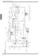
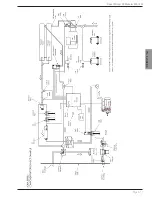
High Pressure Manifold connects the High
Pressure Hose, High Pressure Transducer, High
Pressure Gauge, and Back Pressure Regulator.
BRINE DISCHARGE SECTION:
The Brine Discharge Section carries the Brine Discharge
water, exiting from the R.O. Membrane Element, back to
the feed source.
1.
Brine Discharge Flow Meter measures the brine
water rate of flow from the R.O. Membrane
Element in gallons or liters per hour. By adding
the amount of Product Water flow to the Brine
Discharge Flow the operator is able to determine
the total Feed Water Flow.
2.
Brine Discharge T-Connector collects the brine
discharge water and unpotable product water.
3.
Brine Discharge Connector attaches to the over
board thru-hull fitting for connecting the brine
discharge hose.
4.
Multi Media Filter Waste “T” *** is included with
the Multi Media Filter. This waste T is installed
in line at the Brine Discharge fitting to allow
discharge of the waste from the Multi Media Filter
during the back wash and rinse operations, and
the brine discharge water from the system.
5.
Thru Hull Brine Discharge Fitting ** should be
installed above water level for discharge of the
Brine Discharge Water from the system.
PRODUCT WATER SECTION:
The Product Water Section gives a visual indication of
the clarity, quantity, and quality of the product water.
Post Filtration is the final step in Product Water quality
control. The Post Filtration Subsystem is designed to
limit unpleasant odor and taste, adjust the pH to neutral,
and sterilize biological matter which may have passed
through the R.O. Membrane Element.
1.
Product Water T-Connector combines the
product water from the two individual R.O.
Membrane Elements.
2.
Temperature Compensated Salinity Probe
electronically determines whether the salinity
content of the Product Water is acceptable.
This Salinity Probe is temperature compensated
and provides an accurate measurement of
Product Water quality.
3.
Flow Meter, Product Water electronically measures
the rate of Product Water flow, in gallons or liters
per hour.
4.
3-Way Product Water Diversion Valve, Electric
Solenoid Actuated. The Controller energizes this
valve to the “Potable” position when the system
produces water which meets the low salinity
requirement. If the Product Water being produced
is “Unpotable”, or high in salinity, then no signal is
sent to the valve, and it thus remains in the normal
open position. The “fail safe” normal open position
diverts the unpotable Product Water to discharge.
5.
Charcoal Filter removes foul odors from the
Product Water. Sulfurous odor (rotten egg smell) is
caused when biological matter dies and decays in
the feed water section. Fresh water flushing of the
system helps to minimize this odor.
6.
pH Neutralizer Filter The pH value of pure water
is pH7 which is regarded as neutral. pH values
from 0-7 indicate acidity and pH values from 7-14
indicate alkalinity. The product water from an R.O.
System will be slightly acidic because most of the
naturally occurring high pH calcium carbonate has
been removed. The product water from an R.O.
System will also be very soft for the same reason.
The product water pH will be approximately 6.5
pH. The pH Neutralizer Filter dissolves calcium
carbonate back into the product water bringing the
pH level to neutral at approximately pH 7.
7.
Ultra Violet Sterilizer *** sterilizes at least 99.9%
of any virus, bacteria, and other micro-organisms
which may pass through the R.O. membrane
element. The UV sterilizer is recommended if
the Product Water Storage Tank is not otherwise
treated by means such as chlorination.
8.
Product Water Connector attaches to the Potable
Water unpressurized tank for connection of the
Product Water hose.
FRESH WATER SYSTEM
The Fresh Water System represents the boat or home’s
fresh water pressurized system. Pressurized fresh water
is required to supply the System Fresh Water Flush.
1.
Potable Water Storage Tank** may be any container
suitable for storing Potable Water, i.e. existing
water storage tank on a boat or cistern for a home.
Содержание Aqua Whisper DX 1400-2
Страница 2: ......
Страница 3: ...Aqua Whisper DX Modular 450 1800 Owner s Manual...
Страница 4: ......
Страница 11: ...Introduction Aqua Whisper DX Modular 450 1800 Section 1 INTRODUCTION...
Страница 12: ...Introduction...
Страница 15: ...Description Aqua Whisper DX Modular 450 1800 Section 2 SYSTEM DESCRIPTION...
Страница 16: ...Description...
Страница 21: ...Aqua Whisper DX Modular 450 1800 Page 2 5 Description COMPLIANCE CERTIFICATES...
Страница 23: ...Aqua Whisper DX Modular 450 1800 Page 2 7 Description...
Страница 25: ...Aqua Whisper DX Modular 450 1800 Page 2 9 Description...
Страница 30: ...Aqua Whisper DX Modular 450 1800 Page 2 14 Description OPTIONAL ACCESSORIES...
Страница 38: ...Aqua Whisper DX Modular 450 1800 Page 2 22 Description This page is intentionally left blank...
Страница 39: ...Aqua Whisper DX Compact 450 1800 Section 3 PRE INSTALLATION NOTES Pre installation...
Страница 40: ...Pre installation...
Страница 56: ...Aqua Whisper DX Modular 450 1800 Page 3 16 Pre installation...
Страница 57: ...Aqua Whisper DX Modular 450 1800 Page 3 17 Pre installation...
Страница 65: ...Aqua Matic Compact 450 1800 Section 4 ELECTRICAL INFORMATION Electrical...
Страница 66: ...Electrical...
Страница 75: ...Aqua Whisper DX Modular 450 1800 Page 4 9 Electrical Electrical Motor Wiring Three Phase...
Страница 80: ...Electrical...
Страница 81: ...Installation Aqua Whisper DX Modular 450 1800 Section 5 INSTALLATION REQUIREMENTS...
Страница 82: ...Installation...
Страница 94: ...Aqua Whisper DX Modular 450 1800 Page 5 12 Installation...
Страница 95: ...Commissioning Aqua Whisper DX Modular 450 1800 Section 6 COMMISSIONING...
Страница 96: ...Commissioning...
Страница 106: ...Aqua Whisper DX Modular 450 1800 Page 6 10 Commissioning...
Страница 107: ...Operation Aqua Whisper DX Modular 450 1800 Section 7 OPERATION...
Страница 108: ...Operation...
Страница 120: ...Aqua Whisper DX Modular 450 1800 Page 7 12 Operation...
Страница 122: ...Aqua Whisper DX Modular 450 1800 Page 7 14 Operation...
Страница 123: ...Aqua Whisper DX Compact 450 1800 Section 8 MAINTENANCE AND REPAIR Maintenance...
Страница 124: ...Maintenance...
Страница 145: ...Troubelshooting Troubelshooting Aqua Whisper DX Modular 450 1800 Section 9 TROUBLESHOOTING...
Страница 146: ...Troubelshooting...
Страница 167: ...Parts View Aqua Whisper DX Modular 450 1800 Section 10 EXPLODED PARTS VIEW...
Страница 168: ...Parts View...
Страница 183: ...Aqua Whisper DX Modular 450 1800 Page 10 15 Parts View...
Страница 191: ...Aqua Whisper DX Modular 450 1800 Page 10 23 Parts View...
Страница 217: ...Sheet 11 3 Aqua Whisper DX Electrical Wiring Diagram 110 120 VAC 50 60 HZ Single Phase...
Страница 218: ...Sheet 11 4 Aqua Whisper DX Electrical Wiring Diagram 110 120 VAC 50 60 HZ Single Phase with Soft Start...
Страница 219: ...Sheet 11 5 Aqua Whisper DX Electrical Wiring Diagram 208 240 VAC 50 60 HZ Single Phase...
Страница 220: ...Sheet 11 6 Aqua Whisper DX Electrical Wiring Diagram 208 240 VAC 50 60 HZ Single Phase with Soft Start...
Страница 221: ...Sheet 11 7 Aqua Whisper DX Electrical Wiring Diagram 200 240 VAC 50 60 HZ Three Phase...
Страница 222: ...Sheet 11 8 Aqua Whisper DX Electrical Wiring Diagram 200 240 VAC 50 60 HZ Three Phase with Soft Start...
Страница 223: ...Sheet 11 9 Aqua Whisper DX Electrical Wiring Diagram 380 460 VAC 50 60 HZ Three Phase...
Страница 224: ...Sheet 11 10 Aqua Whisper DX Electrical Wiring Diagram 380 460 VAC 50 60 HZ Three Phase with Soft Start...
Страница 225: ......


