background image

Installation and adjustment 


24


2010-09-15 

 FM 239 MuW Beta Type Z Rev.01 


Procedure 

1. 

Connect the power to the limit switches. 

2. 

Slacken the bracket fixing screw (figure 5). 

3. 

Run the carriage as far as the safety zone. 

4. 

Move the limit switch until it trips. 

5. 

Tighten the bracket fixing screw. 

6. 

Check the correct position of the limit switch: Move the carriage 
manually and observe the switching operation.  
If the braking distance is too short, repeat the set-up. 


6.4 

Mounting a drive unit 


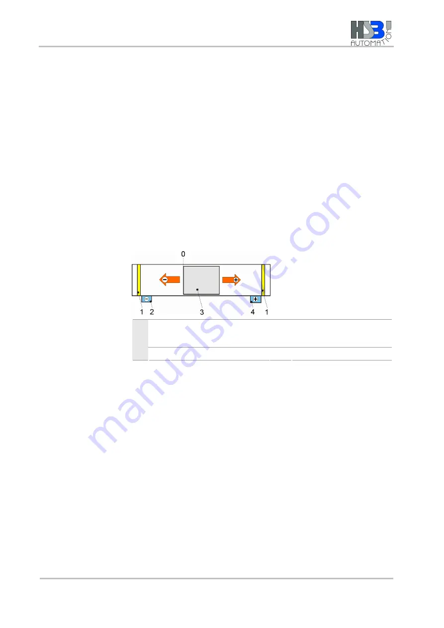
Make sure the direction of rotation of the external drive unit takes into 
account the direction of the spindle or timing belt so that the limit 
switches work correctly. 


Safety zone 

Carriage with positive and 
negative directions from 
reference point 0 

Key


Negative limit switch 

Positive limit switch 


Figure 7: Example of travel direction and limit switch configuration 

Содержание RPE 100

Страница 1: ...01 A RPE en 2011 08 04 SK CW Document last updated 2011 02 15 Three dimensional gantry electric RPE 100 RPE 200 Assembly and Operating manual ...

Страница 2: ...ng results to the customer s complete satisfaction SCHUNK products are inspiring Our detailed assembly and operation manual will support you Do you have further questions You may contact us at any time even after purchase You can reach us directly at the mentioned addresses in the last chapter of these instructions Kindest Regards Your SCHUNK GmbH Co KG Precision Workholding Systems Bahnhofstr 106...

Страница 3: ... 3 Obligations of the manufacturer operator 9 2 3 1 Choice of personnel and personnel qualifications 9 2 3 2 Organizational measures 10 2 3 3 Disposal 10 2 4 Personnel responsibilities 11 2 4 1 Safety conscious working 11 2 4 2 Safety measures during transport 11 2 4 3 Safety measures during operation 11 2 4 4 Behaviour in the event of faults and or emergencies 11 2 4 5 Testing inspections 11 2 5 ...

Страница 4: ...ndling modules 18 7 Maintenance and repair 19 8 Troubleshooting 20 9 Component documentation 20 10 Translation of original EC declaration of incorporation 21 11 Contacts 22 Appendix on CD ROM Documentation Linear axis Beta Appendix 1 Documentation Drive MSK Appendix 2 ...

Страница 5: ...quire personnel to read and observe this manual and the applicable documents especially the safety notes and warnings Skilled personnel fitter Read observe and follow this manual and the applicable documents especially the safety notes and warnings Tab 1 1 3 Applicable documents Detailed device documentation is included in the unit s scope of delivery Document Purpose See Component documentation T...

Страница 6: ...vance can cause slight injuries NOTICE Information on avoiding material damage Handling instruction also measures in a warning or note Tab 3 1 5 Copyright This manual remains the copyrighted property of SCHUNK GmbH Co KG It is solely supplied to our customers and op erators of our products and forms part of the unit This documentation may not be duplicated or made accessible to third parties in pa...

Страница 7: ...rve the technical data and installation and operation notes in this manual and to comply with the maintenance intervals Any other use or use exceeding that specified is an infringement of use for intended purpose The manufacturer bears no liability for damage resulting from such use Use which is not specified as an intended use is for instance when the unit is used with machines systems or workpie...

Страница 8: ...ly remedy faults that could impair safety In addition to this manual statutory and other safety and accident prevention regulations and the standards and guidelines valid at the usage site must be complied with 2 2 1 Protective equipment When the unit is in use when in rotation and when it is stationary protective equipment must be used to catch flying parts should the unit or part of the unit fai...

Страница 9: ...e adequately and appropriately trained to perform the work on the unit allocated to them Every person called upon by the operator to work on the unit must have read and understood the complete Assembly and Op erating Manual especially chapter 2 Basic safety notes This applies particularly to occasional personnel such as maintenance personnel We recommend that the manufacturer operator require empl...

Страница 10: ...in the direct vicinity of the machine system where the unit is installed and that it is accessible for the relevant persons Ensure that personnel have read and understood this manual especially chapter 2 Basic safety notes Provide instruction about and observe the safety and accident prevention regulations valid at the usage site Provide instruction about and observe the environmental protection r...

Страница 11: ...fitted and is in full working order Check the unit at least once per shift for externally visible damage and faults Report any changes including changes in operational behaviour to the responsible place persons immediately If necessary immediately shut down and lock out the machine system 2 4 4 Behaviour in the event of faults and or emergencies If faults on the unit occur which could impair safet...

Страница 12: ...d straps Mount the unit so that it will cause no harm by tilting over or falling down Risk of injury due to uncontrolled movements of the unit when malfunction of the sensors and electrical distribution panelboard Observe the correct connection of the sensors and electrical distributors Risk of injury due to squeezing and clamping between the slide and the base plate during movement of the modules...

Страница 13: ... operation Claims under warranty are excluded when repair or intervention is carried out by persons not authorized to do so This also applies if accessories and spare parts are used which are not designed for our unit 4 Technical Data Reference value Value noise level dB A 70 ambient temperature C 0 to 80 permissible payload kg Three dimensional gantry electric RPE 100 10 Three dimensional gantry ...

Страница 14: ...Configuration 14 01 RPE en 2011 08 04 SK CW 5 Configuration The unit consists of following components 1 3 4 9 8 6 7 1 5 2 Fig 1 ...

Страница 15: ...on 5 mm with 2x proximity switch IN each Documentation Linear axis Beta Appendix 1 Documentation Sensors Appendix 4 6 RPE 100 Linear axis Beta 100D ZSS with toothed beld drive feed rotation 160 mm RPE 200 Linear axis Beta 100D ZSS with toothed beld drive feed rotation 220 mm with 2x proximity switch IN each Documentation Linear axis Beta Appendix 1 Documentation Sensors Appendix 4 7 Drive MSK 040 ...

Страница 16: ...sembly Secure unit during assembly with adequately sized straps Note the tightening torque of fixing screws WARNING Risk of injury when the machine system moves unexpectedly by moving of the linear axis Switch off power supply before assembly and maintenance Make sure that there is no more residual energy in the system The mechanical connection hast o be carried out at the linear axis Beta 80 ZSS ...

Страница 17: ... provided by SCHUNIK and their mechanical connection or without motors flanges and couplings Information on connection of the motors contains the Project Planning Manual MSK Appendix 3 Chapter 8 6 3 Connection of Sensors WARNING Risk of injury when the machine system moves unexpectedly Switch off power supply Make sure that there is no more residual energy in the system WARNING Risk of injury due ...

Страница 18: ...not contribute any excessive forces and torques during assembly of loads The evenness of the mounting surface must be less than 0 02 mm Choose a proper connection with a load that has his own guide mechanism and align them adequately Avoid contact with the linear gantry during operation Select appropriate tightening torques for the assembly of the gantry module or loads at the gantry module in acc...

Страница 19: ...ly visible damages or wear or con tamintion of the system The maintenance intervals apply to the single components ac cording their servicing manuals The component documentation contains maintenance and repair information Component See Linear axis Beta 60 SSS Linear axis Beta 80 SSS Maintenance manual Beta 60 80 SRS SSS Appendix 1 chapter 10 from page 32 Linear axis Beta 80 ZSS Linear axis Beta 10...

Страница 20: ...mponent documentation contains troubleshooting informa tion 9 Component documentation The scope of delivery includes the documentation for the follow ing components see CD ROM Appendix 1 2 Components Manufacturer Appendix Linear axis Beta SCHUNK 1 Drive MSK SCHUNK 2 Tab 7 ...

Страница 21: ...ne into which the incomplete machine is to be installed with the provisions of the Machinery Directive 2006 42 EC is confirmed Applied harmonized standards especially EN ISO 12100 1 Safety of machines Basic concepts general principles for design Part 1 Basic terminology methodology EN ISO 12100 2 Safety of machines Basic concepts general principles for design Part 2 Technical principles The manufa...

Страница 22: ... 86 21 51760266 Fax 86 21 51760267 info cn schunk com www cn schunk com FRANCE SCHUNK Intec SARL Parc d Activités des Trois Noyers 15 Avenue James de Rothschild Ferrières en Brie 77614 Marne la Vallée Cedex 3 Tel 33 1 64 66 38 24 Fax 33 1 64 66 38 23 info fr schunk com www fr schunk com INDIA SCHUNK Intec India Private Ltd 80 B Yeswanthpur Industrial Suburbs Bangalore 560 022 Tel 91 80 40538999 Fa...

Страница 23: ...chunk com RUSSIA OOO SCHUNK Intec ul Samojlovoj 5 lit C St Petersburg 192102 Tel 7 812 326 78 35 Fax 7 812 326 78 38 info ru schunk com www ru schunk com SPAIN PORTUGAL SCHUNK Intec S L U Foneria 27 08304 Mataró Barcelona Tel 34 937 556 020 Fax 34 937 908 692 info es schunk com www es schunk com TURKEY SCHUNK Intec Bağlama Sistemleri ve Otomasyon San ve Tic Ltd Şti Küçükyali Iş Merkezi Girne Mahal...

Страница 24: ...24 01 RPE en 2011 08 04 SK CW ...

Страница 25: ...Appendix 1 Linear axis Beta ...

Страница 26: ...2 01 LPE de 2011 03 18 SK CW ...

Страница 27: ......

Страница 28: ......

Страница 29: ......

Страница 30: ......

Страница 31: ......

Страница 32: ... 0049 7121 14498 10 Info HSB Automation de www HSB Automation de Assembly and Maintenance Manual Linear Unit Types Beta 60 SGV SSS Beta 70 C SRS SSS Beta 80 SRS SSS Beta 80 SGV Beta 100 D SSS Beta 110 SRS SSS Beta 110 C SGV Beta 140 SRS SSS Beta 140 C SSS Beta 165 SSS Beta 165 SGV Beta 165 C SGV Beta 180 SSS Beta 180 C SRS SSS ...

Страница 33: ......

Страница 34: ...anty 7 3 Technical data Standard model 8 4 Product description 17 5 Transportation and storage 20 6 Installation and adjustment 21 6 1 Installing the linear unit by mounting rails 21 6 2 Screwing the linear unit into place from below 22 6 3 Setting maximum travel 22 6 3 1 Setting the positions of the inductive limit switches 22 6 3 2 Setting the positions of the mechanical limit switches 24 6 4 Mo...

Страница 35: ...ith spindle drive Beta 60 SGV SSS Beta 70 C SRS SSS Beta 80 SRS SSS Beta 80 SGV Beta 100 D SSS Beta 110 SRS SSS Beta 110 C SGV Beta 140 SRS SSS Beta 140 C SSS Beta 165 SSS Beta 165 SGV Beta 180 SSS Beta 180 C SRS SSS The drawings show the Beta 60 SSS type and serve as examples for all other types though some of the details may differ ...

Страница 36: ...ates minor risk Failure to observe this notice may result in light to moderate injury or damage to property E Note Indicates tips on use of the machine and optimising its efficiency 1 2 Regulation use The mechanical linear unit is intended for installation in machines and is used solely for manipulating positioning transporting palletising loading unloading clamping clocking tensioning testing mea...

Страница 37: ...with a vent hole generally G1 8 at the basic profile The following guidelines must be observed The linear unit must be subjected to a negative pressure of 0 8 bar The linear unit must be relubricated with a grease suitable for use in clean rooms basic lubrication carried out using Klüberplex BE11 462 1 5 Use in explosive environments If the linear units are used in potentially explosive environmen...

Страница 38: ...ust explosion hazard zone additionally with a monitored compressed air supply Loading Pressure Frequency etc 1 6 Technical condition of the linear unit State of the art The unit conforms to the current state of the art and applicable rules and regulations The unit conforms to the EU Machinery Directive harmonised European standards or corresponding national standards Machinery Directive 2006 42 EC...

Страница 39: ...trained electricians Such work includes Installing safety limit switches Mounting a drive unit Checking the direction of rotation of the drive 1 9 Obligations of the operating company Instruction of personnel In accordance with EU Health and Safety Directive 89 655 EEC articles 6 1 and 7 and with the Framework Directive 89 391 EEC articles 1 1 and 6 1 the company operating the linear unit must pro...

Страница 40: ...er will be voided if the unit is not operated in accordance with the stipulated regulation use the instructions set out in this operating manual are not followed the unit is modified without the consent of the manufacturers screws sealed by locking varnish are unlocked The manufacturer s warranty in respect of maintenance and repair work applies only if original replacement parts are used ...

Страница 41: ...ue Nm 0 70 0 35 0 40 Maximum travel standard mm 5120 2730 Repeat accuracy mm 0 03 0 03 0 03 0 03 Operating temperature C continuous operation 0 80 0 80 Geometrical moment of inertia IY mm 4 473055 585283 563059 Geometrical moment of inertia IZ mm 4 577258 854713 852507 Length of standard carriage mm 180 180 190 Length of long carriage mm 230 240 Weight without travel kg 4 30 3 65 3 65 3 50 Weight ...

Страница 42: ...0 1 00 1 30 Maximum travel standard mm 5020 5060 Repeat accuracy mm 0 03 0 03 0 03 0 03 Operating temperature C continuous operation 0 80 0 80 0 80 0 80 Geometrical moment of inertia IY mm 4 1294343 1372019 917779 Geometrical moment of inertia IZ mm 4 1732340 1677956 2328911 Length of standard carriage mm 210 210 Length of long carriage mm 270 270 Weight without travel kg 5 40 6 20 12 50 6 20 Weig...

Страница 43: ...1 50 Maximum travel standard mm 4920 4920 Repeat accuracy mm 0 03 0 03 0 03 Operating temperature C continuous operation 0 80 0 80 Geometrical moment of inertia IY mm 4 5114812 4974348 4974348 Geometrical moment of inertia IZ mm 4 6177042 5898662 5898662 Length of standard carriage mm 320 320 Length of long carriage mm 500 Weight without travel kg 12 50 13 50 15 40 Weight per 100 mm travel kg 1 40...

Страница 44: ...50 3 00 Maximum travel standard mm 4920 4910 Repeat accuracy mm 0 03 0 03 0 03 0 03 Operating temperature C continuous operation 0 80 0 80 Geometrical moment of inertia IY mm 4 3159202 25391136 Geometrical moment of inertia IZ mm 4 9975915 31673479 Length of standard carriage mm 320 400 Length of long carriage mm 500 600 Weight without travel kg 14 00 15 00 37 90 35 00 Weight per 100 mm travel kg ...

Страница 45: ... 2 50 Maximum travel standard mm 4920 4930 4930 Repeat accuracy mm 0 03 0 03 0 03 0 03 Operating temperature C continuous operation 0 80 0 80 0 80 Geometrical moment of inertia IY mm 4 3127894 9236448 9236448 Geometrical moment of inertia IZ mm 4 9071334 23586987 23586987 Length of standard carriage mm 320 380 380 Length of long carriage mm 500 600 600 Weight without travel kg 15 00 35 00 37 00 33...

Страница 46: ...100 D SSS 4000 1800 4000 3000 350 750 750 1 5 Beta 110 C SGV 16000 1 5 Beta 110 SRS 6000 3000 5000 2500 400 800 600 1 5 Beta 110 SSS 6000 2000 8000 4000 300 600 450 1 Beta 140 SRS 6000 2500 5000 3000 350 700 700 1 5 Beta 140 SSS 6000 2500 6000 4000 500 1000 1000 1 8 Beta 140 C SSS 6000 3200 7500 5000 600 1200 1200 1 8 Beta 165 SGV 18000 3 Beta 165 SSS 18000 5000 15000 8000 700 1400 1100 3 Beta 180...

Страница 47: ...50 C 12 5 4400 5 9300 10 15400 Beta 70 Beta 70 C 16 20 7450 5 10500 20 11600 Beta 60 Beta 80 Beta 100 D 20 50 13000 5 12300 10 13200 25 16700 Beta 110 Beta 140 Beta 140 C 25 50 15400 5 21500 10 33400 20 29700 Beta 120 C Beta 180 Beta 180 C 32 40 14900 5 23800 10 38000 20 33300 Beta 165 Beta 110 C SGV 40 40 35000 10 68700 Beta 165 C SGV 50 20 60000 Dynamic load rating of ball screw nut to DIN 69051...

Страница 48: ...0 3 8 340 320 203 383 Beta 120 25 1 2 25160 22800 3 8 340 320 144 324 Beta 120 C 30 1 2 35558 31700 3 8 580 540 184 364 Beta 140 15 2 4 11667 7800 3 8 180 330 72 Beta 140 ASS 15 2 4 11667 7800 3 8 242 322 72 Beta 140 C ZSS 20 2 4 17700 18800 3 8 200 400 76 Beta 140 C ASS 20 2 4 17700 18800 3 8 220 300 76 Beta 140 C SSS 20 2 4 17700 18800 3 8 210 360 76 Beta 165 ZSS 35 1 2 49448 41900 3 8 985 890 1...

Страница 49: ...he figures given are intended as guides For shorter insertion depths the figures must be adjusted accordingly Tightening torques Nm for clutch with clamping hub Size 14 19 24 28 38 Clutch diameter mm 30 40 55 65 80 Screw size M3 M6 M6 M8 M8 Tightening torque Nm 1 34 10 50 10 50 25 00 25 00 Tightening torques Nm for clutch with clamping ring hub Size 14 19 24 28 38 Clutch diameter mm 30 40 55 65 80...

Страница 50: ... 2010 09 15 17 4 Product description Linear unit with spindle drive 1 Fixed bearing 5 Movable bearing 2 Carriage 6 Base profile 3 Lubricating nipple 7 Driver Key 4 Cover band Figure 1 Component assemblies of the Beta 60 linear unit with spindle drive ...

Страница 51: ...uminium base profile a moving carriage supported by a guide element recirculating ball bearing or roller bearing guidance system and a drive element screw or timing belt drive Depending on its design the carriage is able to absorb forces and moments in all directions and is positively connected to the guidance and drive elements by way of the so called drivers The base profile is self supporting u...

Страница 52: ... can be flexibly configured Multiple linear units of the Alpha Beta or Delta type can be arranged two dimensionally 2 axes or three dimensionally 3 axes Driven linear units can be connected to non driven units of the same type by a plate to be able to take large area loads for example ...

Страница 53: ...irment of its functions Risk of damage by heavy jolting or bending Transport the assembled linear unit only with the transit protection fitted To prevent damage during transportation and storage protect the linear unit against shaking and sliding as follows Stow it in a box of sufficient size Use packing Section 3 lists the unit weights Protect the unit against dirt corrosion water and aggressive ...

Страница 54: ... surface Unit parallelism 0 2 mm 1 000 mm E Mounting by the rails with tapped holes in them is the preferable solution for highly dynamic applications where the linear unit has only two attachment points 6 1 Installing the linear unit by mounting rails Figure 3 Mounting rails 1 E The recommended maximum spacing between the mounting rails is 700 mm Procedure 1 Attach the mounting rails 1 loosely in...

Страница 55: ...ves to its full extent beyond the safety zone the transport carrier mounted on it may break away or topple over The linear unit may be destroyed During setup observe the specified safety zone and set the limit switches accordingly Electrical switches may only be connected by qualified electricians E To stop the carriage promptly in the event of an emergency stop allow for adequate braking distance...

Страница 56: ...e is factory marked on the unit by a band 3 Procedure 1 Connect the power to the limit switches 2 Slacken the limit switch fixing screws 3 Run the carriage as far as the braking position 4 Move the limit switch NC contact under the switching cam until it trips and the LED on the sensor goes out 5 Move the carriage away 6 Tighten the limit switch 7 Check the correct position of the limit switch Mov...

Страница 57: ... is possible External shock absorbers must be fitted to protect against mechanical destruction The necessary braking distance Δ B depends on the velocity and deceleration of the carriage The braking distance must be between the switching point of the limit switch and the actual mechanical end position figure 5 1 Mechanical limit switches 2 Switching cam 3 Band marking safety zone 4 Bracket Key B B...

Страница 58: ...it switch Move the carriage manually and observe the switching operation If the braking distance is too short repeat the set up 6 4 Mounting a drive unit Make sure the direction of rotation of the external drive unit takes into account the direction of the spindle or timing belt so that the limit switches work correctly 1 Safety zone 3 Carriage with positive and negative directions from reference ...

Страница 59: ... the safety limit switches figure 6 Alter the direction of the motor as necessary 3 If the clutch diameter is less than the measure D on the motor housing 4 first mount clutch half 1 1 hole flush with drive shaft and then the motor housing 4 figure 7 If the clutch diameter is greater than the measure D on the motor housing 4 first mount the motor housing 4 and then the clutch half 1 1 hole flush w...

Страница 60: ...taining fixtures conform to the mass and acceleration data provided by the manufacturers Make sure the machine or line into which the linear unit is installed conforms to the EU Machinery Directive the harmonised European standards or applicable national standards Make sure the linear unit is correctly installed Make sure the inductive and or mechanical limit switches are correctly connected and w...

Страница 61: ...n bodies such as by installing deflectors baffle plates or air barriers Duty of inspection The proper functioning of the linear unit must be checked periodically during operation The responsible personnel must check the linear unit and the line for external signs of damage and defects at least once every shift If changes occur which are detrimental to safety shut down the line immediately 9 Shutdo...

Страница 62: ... are key to determining the exact lubrication intervals required Loading Velocity Motion Operating temperature Degree of dirtying Short lubrication intervals Short lubrication intervals are necessary where there is susceptibility to dust and damp under major loading when running at high velocity up to Vmax when running over short travel distances Initial lubrication E Carry out an initial lubricat...

Страница 63: ... categories of lubrication point are identified by the markings S F O on the unit There is a separate lubrication schedule for each lubrication point category Lubrication point category Lubrication for Lubricant S Spindle Grease F Guide elements Grease O Guide elements Oil Lubrication method Lubrication should as far as possible take place while the unit is running so that the grease is distribute...

Страница 64: ... 40 2525 3 10 2550 4 80 3205 4 20 3210 13 10 3220 8 40 3232 5 30 3240 25 000 000 3 00 4005 5 30 4010 15 40 4020 10 20 4040 15 000 000 9 50 BSD Ball Screw Drive Or at least 2x per year The lubrication interval depends on the ambient temperatures and on the loading see figure 11 Relubrication in motion Greases to DIN 51825 KPE1R 20 e g Klüberplex BE 31 102 E If other greases are used pay attention t...

Страница 65: ...reases to DIN 51825 KPE1R 20 e g Klüberplex BE 31 102 E If other greases are used pay attention to manufacturers specifications E Greases containing solid lubricant e g graphite MoS2 must not be used Or at least 2x per year The lubrication interval depends on the ambient temperatures and on the loading see figure 11 Relubrication in motion Figure 10 Relubrication intervals for the linear guidance ...

Страница 66: ... Lubrication interval Oil quantity cm Oil type Every 2 000 km approx 0 4 Oil to DIN 51825 KPE1R 20 e g Febis K68 or INTERFLON fin super E If other oils are used pay attention to manufacturers specifications Or at least 2x per year The lubrication interval depends on the ambient temperatures and on the loading ...

Страница 67: ...inear unit components during installation and assembly E Do not damage the standard parts screws pins etc or the dismantled components they will be refitted E If cover bands are worn also replace the band guide elements If cover bands are damaged check the band guide elements for wear and replace them only as necessary 1 Clamp fittings 2 Carriage 3 Cover band Key 4 Lubricating nipple Figure 11 Cov...

Страница 68: ...t be refitted in the same position E Do not lose the O rings fitted on the lubricating apertures on the inside of the carriage 3 Detach the clamp fittings from the ends of the cover band and remove the cover band 4 Check the band guide elements such as the press rollers a lifting rollers b and locating pins for wear If the cover band is worn be sure also to replace the band guide elements Worn gui...

Страница 69: ...9 To check that the carriage is correctly installed run it slowly from one end of the linear unit to the other ensuring the cover band is held all the time in its guideway 10 Fit the lubricating nipples On Beta 60 to 80 Insert the screw fit lubricating nipples On Beta 60 to 80 Fit the lubricating adapters and then the conical lubricating nipples or the external lubrication ports On Beta 100 to Bet...

Страница 70: ... 0 Fax 0049 7121 14498 10 Info HSB Automation de www HSB Automation de Assembly and Maintenance Manual Linear Unit Types Beta 60 ZSS Beta 70 C ZRS ZSS Beta 80 ZRS ZSS Beta 80 C ZSS Beta 100 ZRS ZSS Beta 100 D ZSS Beta 110 ZRS ZSS Beta 120 ZRS ZSS Beta 140 ZRS ZSS Beta 140 C ZSS Beta 165 ZSS Beta 180 ZSS Beta 180 C ZRS ZSS ...

Страница 71: ......

Страница 72: ...l data Standard model 9 4 Product description 16 5 Transportation and storage 19 6 Installation and adjustment 20 6 1 Installing the linear unit by mounting rails 20 6 2 Screwing the linear unit into place from below 21 6 3 Setting maximum travel 21 6 3 1 Setting the positions of the inductive limit switches 22 6 3 2 Setting the positions of the mechanical limit switches 23 6 4 Mounting a drive un...

Страница 73: ...timing belt drive Beta 60 ZSS Beta 70 C ZRS ZSS Beta 80 ZRS ZSS Beta 80 C ZSS Beta 100 ZRS ZSS Beta 100 D ZSS Beta 110 ZRS ZSS Beta 120 ZRS ZSS Beta 140 ZRS ZSS Beta 140 C ZSS Beta 165 ZSS Beta 180 ZSS Beta 180 C ZRS ZSS The drawings show the Beta 60 ZSS type and serve as examples for all other types though some of the details may differ ...

Страница 74: ...ates minor risk Failure to observe this notice may result in light to moderate injury or damage to property E Note Indicates tips on use of the machine and optimising its efficiency 1 2 Regulation use The mechanical linear unit is intended for installation in machines and is used solely for manipulating positioning transporting palletising loading unloading clamping clocking tensioning testing mea...

Страница 75: ...with a vent hole generally G1 8 at the basic profile The following guidelines must be observed The linear unit must be subjected to a negative pressure of 0 8 bar The linear unit must be relubricated with a grease suitable for use in clean rooms basic lubrication carried out using Klüberplex BE11 462 1 5 Use in explosive environments If the linear units are used in potentially explosive environmen...

Страница 76: ...re Maximum output Speed 1 m s When using a monitored central lubrication system up to 1 5 m s and where the unit is used in a dust explosion hazard zone additionally with a monitored compressed air supply Loading Pressure Frequency etc 1 6 Technical condition of the linear unit State of the art The unit conforms to the current state of the art and applicable rules and regulations The unit conforms...

Страница 77: ...ces must never be dismantled or disabled When fitting special attachments to the unit follow the fitting instructions provided by the manufacturers 1 8 Requirements for personnel The linear unit has been designed and built in accordance with the state of the art and accepted safety standards Hazards may nevertheless be posed when operating it Consequently the unit may only be installed and operate...

Страница 78: ...nies require their personnel to provide written confirmation of having received such instruction Checking the unit In accordance with EU Health and Safety Directive 89 655 EEC article 4a the operating company must subject to the unit to thorough checking prior to putting it into operation after carrying out repairs and after malfunctions have occurred Legibility and maintenance of affixed notices ...

Страница 79: ...er will be voided if the unit is not operated in accordance with the stipulated regulation use the instructions set out in this operating manual are not followed the unit is modified without the consent of the manufacturers screws sealed by locking varnish are unlocked The manufacturer s warranty in respect of maintenance and repair work applies only if original replacement parts are used ...

Страница 80: ... 08 0 08 0 08 0 08 0 08 Operating temperature C continuous operation 0 80 0 80 0 80 0 80 0 80 0 80 0 80 0 80 0 80 Geometrical moment of inertia IY mm 4 400283 858283 563059 1294343 1303940 1782959 917779 Geometrical moment of inertia IZ mm 4 521983 854713 852507 1732340 1680598 3507213 2328911 Length of standard carriage mm 190 190 190 210 210 210 280 280 210 Length of long carriage mm 230 240 240...

Страница 81: ... 08 Operating temperature C continuous operation 0 80 0 80 0 80 0 80 0 80 0 80 0 80 0 80 Geometrical moment of inertia IY mm 4 5114812 4974348 3095671 3159202 3127894 25391136 Geometrical moment of inertia IZ mm 4 6177042 5898662 7114115 9975915 9071334 31673479 Length of standard carriage mm 320 320 320 320 320 320 320 400 Length of long carriage mm 500 500 500 500 500 500 500 600 Weight without ...

Страница 82: ... 7500 7500 Repeat accuracy mm 0 08 0 08 0 08 Operating temperature C continuous operation 0 80 0 80 0 80 Geometrical moment of inertia IY mm 4 9236448 Geometrical moment of inertia IZ mm 4 23586987 Length of standard carriage mm 380 380 380 Length of long carriage mm 600 600 600 Weight without travel kg 37 70 37 70 39 70 Weight per 100 mm travel kg 2 40 1 90 2 60 Weight of standard carriage kg 11 ...

Страница 83: ...1 50 Beta 80 ZSS 1350 800 3000 2000 100 250 250 1 50 Beta 80 C ZSS 2200 1600 4000 3000 300 500 500 1 80 Beta 80 ARS 1000 500 1500 800 50 180 100 1 50 Beta 80 ASS 1000 800 3000 2000 100 250 250 1 50 Beta 100 ZRS 2800 1000 2500 1200 200 250 200 2 50 Beta 100 ZSS 2800 1000 3000 2000 200 250 250 2 50 Beta 100 D ZSS 2200 1800 4000 3000 350 750 750 3 00 Beta 110 ZRS 4000 2000 5000 2500 300 600 450 3 50 ...

Страница 84: ... 180 AZSS 4500 8000 16000 8000 2000 4000 2000 10 00 Beta 180 C ZRS 6000 6000 10000 6000 1200 2000 1200 8 00 Beta 180 C ZSS 6000 8000 15000 8000 1800 3600 1800 8 00 Beta 180 C ARS 3500 6000 10000 6000 1200 2000 1200 8 00 Beta 180 C ASS 3500 8000 15000 8000 1800 3600 1800 8 00 Figures in relate to the long carriage Mno load No load torque 30 The forces and moments quoted are maximum values for the s...

Страница 85: ...0 3 8 340 320 203 383 Beta 120 25 1 2 25160 22800 3 8 340 320 144 324 Beta 120 C 30 1 2 35558 31700 3 8 580 540 184 364 Beta 140 15 2 4 11667 7800 3 8 180 330 72 Beta 140 ASS 15 2 4 11667 7800 3 8 242 322 72 Beta 140 C ZSS 20 2 4 17700 18800 3 8 200 400 76 Beta 140 C ASS 20 2 4 17700 18800 3 8 220 300 76 Beta 140 C SSS 20 2 4 17700 18800 3 8 210 360 76 Beta 165 ZSS 35 1 2 49448 41900 3 8 985 890 1...

Страница 86: ...0 35 4 2 3 000 6 800 202 352 202 389 98 Beta 180 35 4 2 3 000 6 800 272 492 272 492 121 Beta 180 C 47 4 2 6550 13500 224 444 224 444 125 The pre tension per roller is approximately 5 Tightening torques Nm for fixing screws Fixing screws M4 M5 M6 M8 M10 DIN912 ISO4762 8 8 2 7 5 4 9 0 22 0 43 0 DIN912 ISO4762 10 9 3 0 5 7 9 0 22 0 43 0 DIN912 ISO4762 12 9 3 0 5 7 9 0 22 0 3438 0 The figures given ar...

Страница 87: ... Beta Type Z Rev 01 4 Product description Linear unit with timing belt drive 1 Bearing casing 4 Cover band 2 Carriage 5 Base profile Key 3 Lubricating nipple 6 Driver Figure 1 Component assemblies of the Beta 60 linear unit with timing belt drive ...

Страница 88: ...ads quickly safely and precisely from one position to another It consists of an aluminium base profile a moving carriage supported by a guide element recirculating ball bearing or roller bearing guidance system and a drive element screw or timing belt drive Depending on its design the carriage is able to absorb forces and moments in all directions and is positively connected to the guidance and dr...

Страница 89: ...or mechanical limit switches and other fittings see section 6 3 The effective range can be flexibly configured Multiple linear units of the Alpha Beta or Delta type can be arranged two dimensionally 2 axes or three dimensionally 3 axes Driven linear units can be connected to non driven units of the same type by a plate to be able to take large area loads for example ...

Страница 90: ...irment of its functions Risk of damage by heavy jolting or bending Transport the assembled linear unit only with the transit protection fitted To prevent damage during transportation and storage protect the linear unit against shaking and sliding as follows Stow it in a box of sufficient size Use packing Section 3 lists the unit weights Protect the unit against dirt corrosion water and aggressive ...

Страница 91: ... surface Unit parallelism 0 2 mm 1 000 mm E Mounting by the rails with tapped holes in them is the preferable solution for highly dynamic applications where the linear unit has only two attachment points 6 1 Installing the linear unit by mounting rails Figure 3 Mounting rails 1 E The recommended maximum spacing between the mounting rails is 700 mm Procedure 1 Attach the mounting rails 1 loosely in...

Страница 92: ...blocks 1 tapped hole rails 3 Tighten the linear unit for tightening torques see section 3 6 3 Setting maximum travel Serious injury may result if the transport carriers topple over If the carriage moves to its full extent beyond the safety zone the transport carrier mounted on it may break away or topple over The linear unit may be destroyed During setup observe the specified safety zone and set t...

Страница 93: ... 2 Switching cam Key 3 Band marking safety zone Figure 5 Inductive limit switches The limit switches must switch so that the carriage comes to a stop immediately before the safety zone The safety zone is factory marked on the unit by a band 3 Procedure 1 Connect the power to the limit switches 2 Slacken the limit switch fixing screws 3 Run the carriage as far as the braking position 4 Move the lim...

Страница 94: ... is possible External shock absorbers must be fitted to protect against mechanical destruction The necessary braking distance Δ B depends on the velocity and deceleration of the carriage The braking distance must be between the switching point of the limit switch and the actual mechanical end position figure 5 1 Mechanical limit switches 2 Switching cam 3 Band marking safety zone 4 Bracket Key B B...

Страница 95: ...it switch Move the carriage manually and observe the switching operation If the braking distance is too short repeat the set up 6 4 Mounting a drive unit Make sure the direction of rotation of the external drive unit takes into account the direction of the spindle or timing belt so that the limit switches work correctly 1 Safety zone 3 Carriage with positive and negative directions from reference ...

Страница 96: ... the safety limit switches figure 6 Alter the direction of the motor as necessary 3 If the clutch diameter is less than the measure D on the motor housing 4 first mount clutch half 1 1 hole flush with drive shaft and then the motor housing 4 figure 7 If the clutch diameter is greater than the measure D on the motor housing 4 first mount the motor housing 4 and then the clutch half 1 1 hole flush w...

Страница 97: ...taining fixtures conform to the mass and acceleration data provided by the manufacturers Make sure the machine or line into which the linear unit is installed conforms to the EU Machinery Directive the harmonised European standards or applicable national standards Make sure the linear unit is correctly installed Make sure the inductive and or mechanical limit switches are correctly connected and w...

Страница 98: ...n bodies such as by installing deflectors baffle plates or air barriers Duty of inspection The proper functioning of the linear unit must be checked periodically during operation The responsible personnel must check the linear unit and the line for external signs of damage and defects at least once every shift If changes occur which are detrimental to safety shut down the line immediately 9 Shutdo...

Страница 99: ... The following factors are key to determining the exact lubrication intervals required Loading Velocity Motion Operating temperature Degree of dirtying Short lubrication intervals Short lubrication intervals are necessary where there is susceptibility to dust and damp under major loading when running at high velocity up to Vmax when running over short travel distances Initial lubrication E Carry o...

Страница 100: ... categories of lubrication point are identified by the markings S F O on the unit There is a separate lubrication schedule for each lubrication point category Lubrication point category Lubrication for Lubricant S Spindle Grease F Guide elements Grease O Guide elements Oil Lubrication method Lubrication should as far as possible take place while the unit is running so that the grease is distribute...

Страница 101: ...reases to DIN 51825 KPE1R 20 e g Klüberplex BE 31 102 E If other greases are used pay attention to manufacturers specifications E Greases containing solid lubricant e g graphite MoS2 must not be used Or at least 2x per year The lubrication interval depends on the ambient temperatures and on the loading see figure 11 Relubrication in motion Figure 10 Relubrication intervals for the linear guidance ...

Страница 102: ... Lubrication interval Oil quantity cm Oil type Every 2 000 km approx 0 4 Oil to DIN 51825 KPE1R 20 e g Febis K68 or INTERFLON fin super E If other oils are used pay attention to manufacturers specifications Or at least 2x per year The lubrication interval depends on the ambient temperatures and on the loading ...

Страница 103: ...parts screws pins etc or the cover band and its elements they will be re used Risk of damage due to lack of lubrication Do not lose or damage the O rings fitted on the lubricating apertures otherwise component lubrication will not be guaranteed 1 Driven bearing casing 8 Non driven bearing casing 2 Timing belt 9 Driver 3 Clamp fitting 10 Base profile 4 Cover band 11 Drive shaft 5 Carriage 12 Timing...

Страница 104: ...arriage It must be refitted in the same position 4 Unscrew the cover band clamp fittings 5 Carefully lift the cover band over the timing belt out of its guideway and remove it 6 Loosen the clamping screws and pull the two timing belt holders out of the driver Do not lose the spacers if fitted 7 Unscrew the non driven bearing casing 8 With single part timing belt holders Unscrew the countersunk scr...

Страница 105: ...ng belt are provided along with the replacement belt Tension the timing belt so that the specified Hz figure is indicated 21 Insert the cover band over the timing belt with its broader side with the chamfered cutting edge facing downwards and fix it at one end by the clamp fitting 22 Carefully press the cover band into its guideway along its entire length until it audibly snaps into place Secure t...

Страница 106: ...t To ensure the cover band engages safely in its guideway slowly move the carriage along its entire travel distance by hand 28 Fit the lubricating nipples On Beta 60 to 80 Insert the screw fit lubricating nipples On Beta 60 to 80 Fit the lubricating adapters and then the conical lubricating nipples or the external lubrication ports On Beta 100 to Beta 180 Fit the lubricating adapter and then the s...

Страница 107: ...inear unit components during installation and assembly E Do not damage the standard parts screws pins etc or the dismantled components they will be refitted E If cover bands are worn also replace the band guide elements If cover bands are damaged check the band guide elements for wear and replace them only as necessary 1 Carriage 2 Clamp fitting 3 Cover band Key 4 Lubricating nipple Figure 12 Cove...

Страница 108: ...t be refitted in the same position E Do not lose the O rings fitted on the lubricating apertures on the inside of the carriage 3 Detach the clamp fittings from the ends of the cover band and remove the cover band 4 Check the band guide elements such as the press rollers a lifting rollers b and locating pins for wear If the cover band is worn be sure also to replace the band guide elements Worn gui...

Страница 109: ...9 To check that the carriage is correctly installed run it slowly from one end of the linear unit to the other ensuring the cover band is held all the time in its guideway 10 Fit the lubricating nipples On Beta 60 to 80 Insert the screw fit lubricating nipples On Beta 60 to 80 Fit the lubricating adapters and then the conical lubricating nipples or the external lubrication ports On Beta 100 to Bet...

Страница 110: ...Appendix 2 Drive MSK ...

Страница 111: ...2 01 LPE de 2011 03 18 SK CW ...

Страница 112: ...netseite von Rexroth heruntergeladen werden www boschrexroth com Dokumentation und Downloads Suchbegriff R911296288 Project Planning Manual Rexroth IndraDyn S Synchronous Motors MSK The Project Planning Manual for Synchronous Motors MSK can be downloaded from the website of Rexroth www boschrexroth com Search Keyword R911296289 DE EN ...

Отзывы: