STB8827
Series Operation Manual Chapter 5 Execute LCR Operation and Some Examples
test leads will directly change stray capacitance and inductance on test terminals
and this problem is unavoidable, because the test leads cannot be fixed in a
54
position.
So, the use of the test fixture should be used as possible in high frequency. If
the test fixture is unavailable or cannot be used, the status of test leads should be
the same in the processes of correction and test.
No matter the standard Kelvin test fixture or Kelvin test leads or user-made
fixture is used, the following requirements should be met.
1. Distribution impedance must be reduced to the Min. especially when testing
high impedance components.
2. Contact resistance must be reduced to Min.
3. Short and open must be available between contact points. Open and short
correction can easily reduce the influence of distribution impedance of the test
fixture on measurement. For open correction, the clearance between test
terminals should be the same with that when they connects with DUT. For short
correction, the short plate of low impedance should be connected between test
terminals. Another way is to directly connect Hc with Lc or Hp with Lp, then
connect both.
Note:
When the DUT is a polarity component, before testing, the high potential
terminal should be connected to the terminal with mark “+”, “Hc” or “Hp” and the
low terminal should be connected to the terminal with mark “-”, “Lc” or “Lp”.
Warning: Before testing, please discharge the tested polarity component
so as to avoid the damage to the instrument.
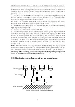
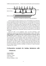
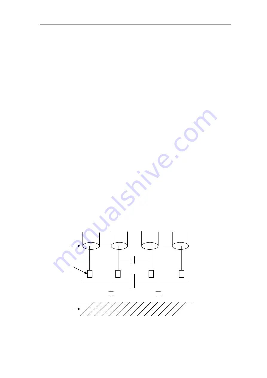
5.3 Eliminate the influence of stray impedance
Hc Hp Lp Lc
Shielding ground
Cd
Test terminal
Cx
Ch Cl
Metal conductor
Figure 5-1 Influence of stray capacitance

