STB8827
Series Operation Manual
Contents
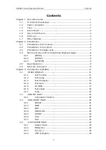
5.1.1 Sweep
correction ...................................................... 52
5.1.2 Point-freque
IV
ncy correction.......................................... 52
5.2
Correct connection of DUT..................................................... 53
5.3
Eliminate the influence of stray impedance .............................. 54
5.4
Operation example for testing inductance with
STB8827
A ...........
55
5.5
Operation example of testing capacitance by multi-frequency
list sweep 57
5.6
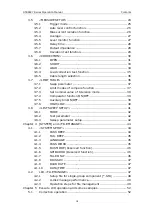
Transformer Measurement..................................................... 59
5.6.1
Primary and secondary inductance L2A, L2B ................. 60
5.6.2
Turn ratio and polarity measurement N, 1/N ................. 60
5.6.3 Mutual
inductance M ................................................. 61
5.6.4
Direct current resistance measurement R2, DCR ........... 61
5.6.5 Leakage
inductance Lk .............................................. 62
5.6.6 Winding
capacitance Co ............................................. 62
5.7
Setup example of comparator ................................................ 62
5.7.1 Capacitor sorting ...................................................... 63
5.8
Operation example of load correction ...................................... 64
Chapter 6 Performance and Test ........................................................... 66
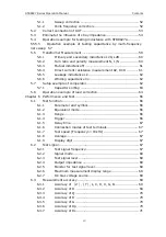
6.1 Test
function ....................................................................... 66
6.1.1 Parameter
and
symbol
............................................... 66
6.1.2 Equivalent mode ....................................................... 66
6.1.3 Range ..................................................................... 66
6.1.4 Trigger .................................................................... 66
6.1.5 Delay
time ............................................................... 67
6.1.6
Connection modes of test terminals ............................. 67
6.1.7
Test speed (Frequency>=10kHz) ................................ 67
6.1.8 Average
................................................................... 67
6.1.9 Display digit ............................................................. 67
6.2 Test
signal .......................................................................... 67
6.2.1
Test signal frequency ................................................. 67
6.2.2 Signal
mode
............................................................. 68
6.2.3 Test
signal level ........................................................ 68
6.2.4 Output
impedance .................................................... 68
6.2.5
Monitor for test signal level ........................................ 68
6.2.6 Maximum
measurement display range ......................... 68
6.2.7
DC bias voltage source .............................................. 69
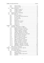
6.3 Measurement
accuracy ......................................................... 69
6.3.1 Accuracy
of
│
Z
│
,
│
Y
│
, L, C, R, X, G, B ...................... 69
6.3.2 Accuracy of D ........................................................... 69
6.3.3 Accuracy of Q ........................................................... 70
6.3.4 Accuracy
of
θ
........................................................... 70
6.3.5 Accuracy of G ........................................................... 70
6.3.6 Accuracy of Rp ......................................................... 70
6.3.7
Accuracy of Rs .......................................................... 71


