18
ADJUSTMENTS
—DOOR PANEL ALIGNMENT AND ADJUSTMENT
PHOTO EYE ADJUSTMENT-ALIGNMENT
Unless the photo eyes are knocked out of alignment,
they generally do not require alignment. If the
mounting brackets are intact and positioned as they
were when originally installed and the photo eyes are
not working properly, refer to “PHOTO EYES” on
page 4 for photo eye diagnostic information.
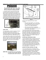
The photo eye transmitter and receiver can be
identified in two ways. The transmitter is designated
SMT3000 on the white label or by a single green light
that comes on at the clear end of the transmitter.
(See Figure 40)
NOTE: When the cable is connected to the photo
eye, there is only a ¹/
₄
-inch window to see
the green or yellow LED light.
Figure 40
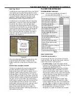
The receiver is designated SMR 3215 on the white
label or by a yellow light that illuminates only when it
is in proper alignment with the transmitter. (See
Figure 41)
Testing Photo Eyes
W
hen the door’s power is on, the green light on the
photo eye transmitter indicates the photo eye module
is powered up. When the yellow light on the photo
eye receiver module is also lit, the emitter and
receiver modules are properly aligned.
Placing your hand in front of the receiver breaks the
light path and should cause the yellow light to go out.
Removing your hand from the light path should
cause the yellow light to go back on if everything is
properly installed and operating correctly.
Troubleshooting Photo Eyes
If the green light does not light, check to make sure
the power is turned on, and that all wiring has
continuity and is installed and connected correctly. If
the green light is on but the yellow light is off, check
the alignment of the emitter and receiver modules
and clean each eye using window cleaner and a soft,
clean cloth.
Figure 41
1. Turn on the power to the door.
2. Move the door to the half-open position.
Take precautions to prevent the door from being
operated as you perform the following procedure.
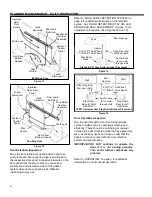
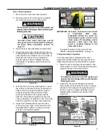
3. Locate the photo eye set. The photo eyes that
monitor the front side of the door are located in
the heavy-duty mounting brackets on the wall,
adjacent to the door panel(s). (See Figure 42)
Figure 42
Mounting
Bracket
Mounting Bracket Positioned
with Eyes Aligned Directly Across
from Each Other (Mounting Brackets
on Both Sides of Door Manually
Assisted Egress Door)
Bi-Parting Door Shown/One-Way Door Is the Same
Transmitter
Module
Designation
Power Light
(Green)
Receiver
Module
Designation
Alignment Light
(Yellow)
Содержание Turbo-Slide
Страница 2: ......
Страница 8: ......
Страница 29: ...21 NOTES...
Страница 32: ...PARTS LIST BI PARTING DOOR ASSEMBLY 24 BI PARTING DOOR ASSEMBLY Figure 48 1 2 3 4 6 7 8 9 10 Bi Parting Door 5...

