9
PLANNED MAINTENANCE
—QUARTERLY INSPECTION
Drive Chain Inspection
1. Move the door to the fully closed position.
2. Remove power to the control panel by placing
the fused disconnect in the OFF position.
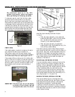
The disconnect must be in the OFF position and
properly locked and tagged before performing the
following procedure.
The drive chain, motor drive gear, and all
idler gears must be lubricated according to
the Drive Chain Lubrication section on
page 10.
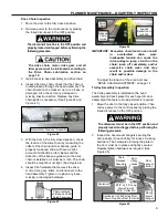
3. Gain access to head assembly and drive chain.
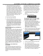
4. Inspect the drive chain. Check that the chain is
routed properly through the head assembly. The
chain should not be cracked, worn, too loose, or
damaged. Also check for any damaged or
missing links/connectors. Replace any drive
chain parts as necessary. (See Figure 22 and
Figure 23.)
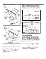
Figure 22
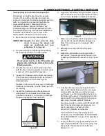
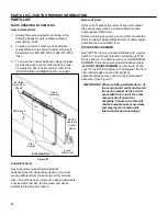
5. With the door in the fully closed position, check
the tension of the drive chain by measuring the
offset of the chain tensioner banana guide. A
properly tensioned chain will have a slight
amount of deflection at its midpoint and the
deflection of the banana guide when the drive
chain is installed on it must be ¼ inch. The chain
should be taught but not tight. (See Figure 24)
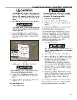
6. Inspect the hardware that secures the drive
motor, drive gear, idlers, and tensioners to the
head assembly. Tighten or replace any loose,
missing, or damaged hardware.
Figure 23
Figure 24
IMPORTANT: Excessive chain tension can result
in
accelerated
chain
wear.
Inadequate tension can cause the
drive pulley to jump a tooth on the
chain, jump off completely, and/or
excessive chain wear, and may
result in possible damage to the
chain and/or door.
To adjust the tension of the drive belt, see
“DRIVE CHAIN ADJUSTMENT” on page 14.
Trolley Assembly Inspection
The trolley assembly is installed on the head
assembly and tracks preset for each specific door
assembly at the factory. No adjustment is required.
1. Move the door to the fully closed position. Then
remove power to the control panel by placing the
fused disconnect in the OFF position.
The disconnect must be in the OFF position and
properly locked and tagged before performing the
following procedure.
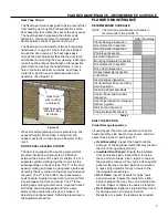
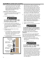
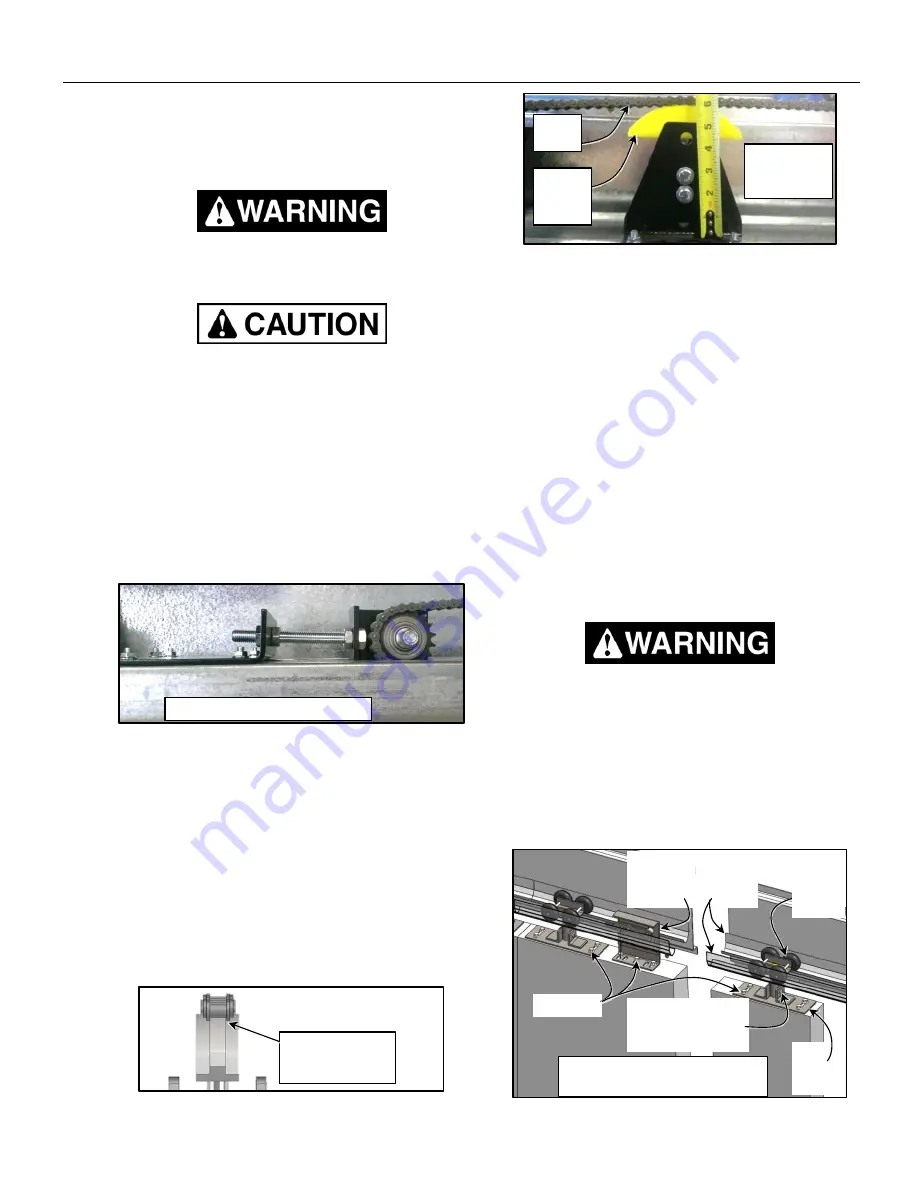
2. Inspect the door swivel hangers securing the
door panel(s) to each trolley for loose or missing
hardware. The hardware clamping the plate to
the door must be in place and tightly secured.
Replace/tighten hardware as required. (See
Figure 25)
Figure 25
Return Idler-Tensioner Assembly
Door
hanger
trolley
Door
swivel
hanger
Door
trolley
tracks
Chain
Release
Assembly
Fasteners
Ø1/2” x 2.25” Long
Clevis Pin with
Ø1/8
” Cotter Pin
Loaded
Deflection: ¼
inch Min.
Sectioned ½ of Bi-Parting Door
Shown,
One-Way Door Is Similar
Chain centered
on Banana Chain
Guide Tensioner
Drive
Chain
Banana
Chain
Guide
Содержание Turbo-Slide
Страница 2: ......
Страница 8: ......
Страница 29: ...21 NOTES...
Страница 32: ...PARTS LIST BI PARTING DOOR ASSEMBLY 24 BI PARTING DOOR ASSEMBLY Figure 48 1 2 3 4 6 7 8 9 10 Bi Parting Door 5...


