19
ADJUSTMENTS
—MOTOR BRAKE
4. Inspect all photo eyes. If a photo eye appears
damaged, bent, or out of position, replace or
readjust the eye or mounting bracket as required.
5. Observe the indicator lights to verify that the
photo eye modules are aligned. The green light
indicates the photo eye transmitter module is
powered up. When the yellow light on the
receiver module is also lit, the emitter and
receiver modules are properly aligned.
MOTOR BRAKE ADJUSTMENT
1. Turn off the power to the door.
The disconnect must be in the OFF position
and properly locked and tagged before
performing the following procedure.
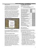
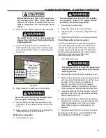
2. Loosen the retaining bolts securing the brake
dust cover to the motor assembly. Remove the
cover. (See Figure 43)
Figure 43
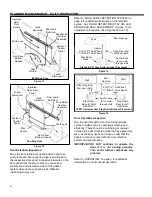
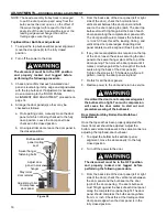
3. To adjust the brake, first securely tighten all
brake adjustment nuts. Then back off each nut
1/2 turn counterclockwise. (See Figure 44)
All nuts must be equally adjusted or the
brake mechanism will wear unevenly.
4. Attach the dust cover and tighten all retaining
bolts.
5. Turn on the power to the door.
6. With all seals adjusted and secured, cycle the
door open and closed several times to test the
seals. Then fully close the door and verify that
the floor sweep seals around the door panel
have remained in place and seal properly against
the floor. Make any necessary adjustments.
Figure 44
CHAIN RELEASE ASSEMBLY ALIGNMENT AND
ADJUSTMENT
The chain release assembly will occasionally need
adjustment as the chain drive and panels are normal
wear items. It generally will require alignment and
adjustment any time the door panel is adjusted or the
drive chain system needs servicing. The Assembly
must be properly aligned with the chain for proper
operation or wear, damage, and/or other
performance problems will occur.
1. Move the door panel(s) to the fully closed
position.
2. Turn off power to door.
The disconnect must be in the OFF position
and properly locked and tagged before
performing the following procedure.
3. Gain access to head assembly and drive chain.
4. After the door panel(s) has been properly
aligned, leveled, elevated, and secured to the
head assembly via the swivel hangers, the drive
chain properly tightened, and the bulb seal
compression properly set, the chain release
mechanism assembly can be aligned with the
drive chain between the idler sprockets and the
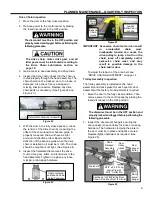
drive. Loosen the fasteners securing the chain
glide bracket and the manual chain release cable
in this assembly. Adjust the height of the bracket
so the chain glide is at the same height as the
chain and level (chain runs level and is not being
lifted or pulled down by it). (See Figure 45)
Dust Cover
Brake Adjustment
Nuts (Three Total)
Dust Cover Retaining
Bolts (Four Total)
Содержание Turbo-Slide
Страница 2: ......
Страница 8: ......
Страница 29: ...21 NOTES...
Страница 32: ...PARTS LIST BI PARTING DOOR ASSEMBLY 24 BI PARTING DOOR ASSEMBLY Figure 48 1 2 3 4 6 7 8 9 10 Bi Parting Door 5...

