13
PLANNED MAINTENANCE
—QUARTERLY INSPECTION
Ensure that the heat tape is not routed near
any moving parts. Also, verify that each
cable is not kinked or twisted and that all
slack is pulled from the entire length of the
cables.
2. Disconnect the power supply from the heat tape.
The electric power must be disconnected and
properly locked and tagged before performing the
following procedure.
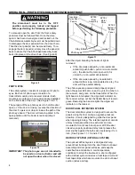
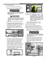
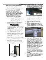
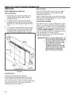
3. Inspect the heat tape that is routed from the
frame header to the junction box. The heat tape
must not be pinched, kinked, or damaged. (See
Figure 32)
Figure 32
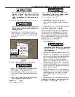
4. Apply power to the heat tape. control panel.
Prevent the door from being operated while
performing the following procedure.
5. Verify that the heat tapes are powered up and
operating. The heat tape should be warm to the
touch.
6. Apply power to the control panel by placing the
fused disconnect in the ON position.
Wall Anchor Inspection
1. Turn off power to door.
The disconnect must be in the OFF position
and properly locked and tagged before
performing the following procedure.
2. Gain access to wall anchors.
3. Inspect for loose or worn wall anchor(s).
4. Tighten, repair, or replace any wall anchors as
needed.
5. Restore power to the door and return to service.
Chain Release Mechanism Inspection
The Chain Release Mechanism Assembly allows
door panel detachment/reattachment to the drive
chain. When detached from the drive chain door
panel(s) may be manually moved. The Assembly
must be properly aligned with the chain for proper
operation or wear, damage, and/or other
performance problems will occur.
1. Turn off power to door.
The disconnect must be in the OFF position and
properly locked and tagged before performing the
following procedure.
2. Gain access to head assembly and drive chain.
3. After the door panel(s) has been properly aligned
and secured to the head assembly via the swivel
hangers and the bulb seal compression is
properly set, check that the chain release
mechanism assembly is aligned with the drive
chain between the idler sprockets and the drive.
4. Check the height of the chain release. It should
operate so the chain runs level and is not being
lifted or pulled down by it.
5. Manual Chain Release Cable must be properly
attached to the pivot arm and door panel handle.
Check for damaged, worn, missing, or loose
parts. Tighten, repair, or replace part(s) as
needed.
6. Restore power to the door and return to service.
If adjustment is necessary, see CHAIN RELEASE
MECHANISM
ADJUSTMENT” on page 19.
Heat Tape
wire routing
in bulb seal
Heat Tape wire
ends to J-Box
by others
Bi-Parting
Door Shown
One-Way Door
Is the Same
Содержание Turbo-Slide
Страница 2: ......
Страница 8: ......
Страница 29: ...21 NOTES...
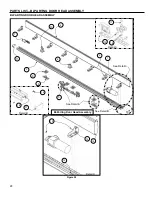
Страница 32: ...PARTS LIST BI PARTING DOOR ASSEMBLY 24 BI PARTING DOOR ASSEMBLY Figure 48 1 2 3 4 6 7 8 9 10 Bi Parting Door 5...


