4
OPERATION
—PHOTO EYES/DOOR RETENTION/DEFROST
The disconnect must be in the OFF
position and properly locked and tagged
before performing the following procedure.
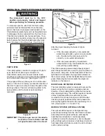
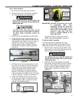
To manually open the door from the front, safety
protocols must be followed first. Once the drive
system has been de-energized and locked out, the
Chain Release Assembly lever must be pulled down
to disengage the door panel(s) from the drive chain.
Then the door panel(s) can be moved freely. To re-
engage the door panel(s), simply move the panel(s)
back to where the Chain Release Assembly locks
back into place on the drive chain. (See Figure 9)
Figure 9
PHOTO EYES
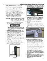
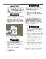
This safety system consists of a single set of photo
eyes. Each set of photo eyes consists of a
transmitter module and a receiver module. Each
module is mounted in a heavy-duty bracket installed
on the front side of the door. (See Figure 10 & 11)
The purpose of these photo eyes is to hold the door
open or, if the door is closing, reverse the direction of
the door if a person or object crosses the path of the
photo eye beam. The door will remain parked in the
open position until the beam is restored (object
removed).
Figure 10
IMPORTANT: The photo eyes are not intended to
be used as a door activator and will
not open the door when it is closed.
Figure 11
After the object breaking the beam of light is
removed:
If the door was opened by a non-automatic
activator (push button, pull cord, radio control,
etc.), the door will remain open until it is
closed by a non-automatic activator.
If the door was opened by an automatic
activator (floor loop, motion detector, etc.), the
door will close automatically.
The photo eyes are powered and properly aligned
when the power indicator on each eye is lit; amber on
the receiver, and green on the transmitter. When the
light beam is interrupted, the alignment indicator on
the receiver will go out but the transmitter will remain
green. Restoring the beam relights the alignment
indicator on the receiver.
DOOR PANEL RETENTION SYSTEM
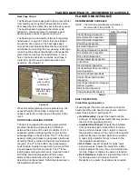
The door retention system is designed to secure the
panels along the floor during a negative pressure
situation. It is also designed to guide the door panel
when opening/closing. The retention system consists
of stay roller assemblies for each door and are
mounted in front of each door panel. With the door
closed a properly positioned stay roller presses the
door slightly against the bulb seal, depressing it ¼-½
inch. (See Figures 11, 15, and/or 16)
DEFROST SYSTEM (OPTIONAL SYSTEM)
The optional defrost system is designed to help
prevent frost build-up in/on the door frame bulb seal
assembly and door panel surfaces, and keep the
seals flexible and pliable in cold temperature
conditions to attain the best seal. A door configured
with a defrost system includes a heat tape circuit and
heat tape strips which are mounted in each bulb seal
section (sides and top).
Rytec
Door
Panels
Rytec
Door
Assembly
Photo eyes
Rytec
Motor
Drive
Rytec
Control
Panel
Photo eye
Stay rollers
Photo eye bracket
Chain
release
lever
Insulated
Rytec Door
Panels
RYTEC
System 4
Control
Panel
RYTEC
Motor
Drive
RYTEC
Door
Assembly
Содержание Turbo-Slide
Страница 2: ......
Страница 8: ......
Страница 29: ...21 NOTES...
Страница 32: ...PARTS LIST BI PARTING DOOR ASSEMBLY 24 BI PARTING DOOR ASSEMBLY Figure 48 1 2 3 4 6 7 8 9 10 Bi Parting Door 5...

