2
INTRODUCTION
—GENERAL ARRANGEMENT OF DOOR COMPONENTS
GENERAL ARRANGEMENT OF DOOR
COMPONENTS
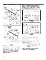
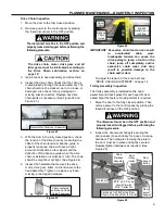
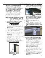
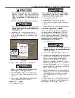
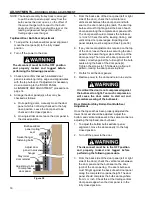
Figure 2 - Figure 5 show the location of the major
components of the door and the general placement
of the associated control sub-assemblies for a typical
installation.
These illustrations are provided to you for
informational purposes only. They should not be
solely relied upon for the operation and maintenance
of your door and its sub-assemblies.
Figure 2
Figure 3
NOTE: Figure 2 and Figure 3 show the front side of
the door. Left and right are determined when
facing/viewing the front side of the door.
This is the side that the door assembly is
mounted on/the same side the head
assembly is on. All views shown on this
page are showing the “Front” side of the
door assembly.
Figure 4, Exploded View
Figure 5
Head
Assembly
Insulated
Rytec
Door
Panels
System 4
Control
Panel
Fused
Disconnect
Photo eyes
Stay
Rollers
Head
Assembly
Insulated
Rytec
Door
Panel
Fused
Disconnect
System 4
Control
Panel
Photo eyes
Stay
Rollers
One-Way Door
Bi-Parting Door
Rytec
Control
Panel
Bulb Seal
Assembly’s
(Top & Sides)
Main Door
Assembly
See Figure 5
Adjustable/replaceable
door panel sweep
Bi-Parting Door Shown
One-Way Door Is Similar
Stay-
Roller
Содержание Turbo-Slide
Страница 2: ......
Страница 8: ......
Страница 29: ...21 NOTES...
Страница 32: ...PARTS LIST BI PARTING DOOR ASSEMBLY 24 BI PARTING DOOR ASSEMBLY Figure 48 1 2 3 4 6 7 8 9 10 Bi Parting Door 5...

