8
PLANNED MAINTENANCE
—QUARTERLY INSPECTION
Mounting Hardware Inspection
1. Move the door to the fully closed position.
2. Remove power to the control panel by placing
the fused disconnect in the OFF position.
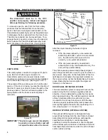
The disconnect must be in the OFF position and
properly locked and tagged before performing the
following procedure.
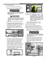
3. Check that the mounting hardware securing the
door header assembly and photo eye mounting
brackets to the wall are in place and tight.
Tighten and replace any loose or missing
hardware, such as wall fasteners, floor anchors,
nuts, bolts, and screws. (See Figure 18)
Figure 18
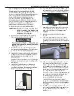
4. Check that all the self-tapping screws used to
secure the bulb seals are tight and in place.
Tighten and replace any loose or missing
hardware. (See Figure 19)
Figure 19
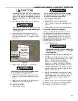
5. Check that all mounting hardware, such as nuts,
bolts, and screws, etc., throughout the head
assembly, drive motor gearbox assembly, idler
assembly, trolleys, mounting brackets, etc. are
secure and tight. Tighten and replace any loose
or missing hardware as necessary. (See Figure
20)
Figure 20
Door Retention Inspection
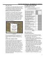
1. Check all mounting hardware associated with the
stay roller door retention system. Check that it is
properly placed. Impact from forklifts, hand
trucks, or other machinery can degrade the
ability of the door system to seal.
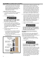
2. Tighten and replace any loose or missing
hardware as necessary. (See Figure 21.)
Figure 21
3. Place the door in the fully closed position.
4. With the stay roller resting on the door panel
closure wedge, the bulb seal should be
depressed ¹/
₄-
¹/
2
inch.
5. As the door opens, the gap at the door bottom
will increase but stay relatively constant at the
top. With the door panel held against the stay
roller, the gap along the entire remaining length
of the bulb seal should remain relatively constant
but increase slightly more as the door opens.
The trolley tracks in the head assembly are
designed to move the door panel up and away
from the bulb seal as it opens.
6. If the door does not meet the above
requirements, refer to “DOOR RETENTION/
STAY ROLLER-DOOR BULB SEAL
ADJUSTMENT” on page 15.
Wall
Fasteners
Bulb Seal
Fasteners
½ of Bi-Parting Door Shown/One-Way Door Is Similar
Bulb Seals
Fasteners
(2 shown)
Содержание Turbo-Slide
Страница 2: ......
Страница 8: ......
Страница 29: ...21 NOTES...
Страница 32: ...PARTS LIST BI PARTING DOOR ASSEMBLY 24 BI PARTING DOOR ASSEMBLY Figure 48 1 2 3 4 6 7 8 9 10 Bi Parting Door 5...


