3
OPERATION
—CONTROL PANEL/POWER DRIVE SYSTEM/MANUAL OPERATION
OPERATION
CONTROL PANEL
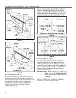
The Turbo Slide door is equipped with a Rytec
System 4 Drive & Control. It is a solid-state,
microprocessor-based, high-speed door control
system designed exclusively to operate Rytec high
performance doors. It provides connections for
multiple activators, close delay timers, status
indicators, as well as a means for programming and
controlling the door and displays status and alarm
messages. All command functions to operate the
drive and control system are software controlled. For
information on control panel operation, see the Rytec
System 4 Drive
& Control Installation & Owner’s
Manual. (See Figure 6)
POWER DRIVE SYSTEM
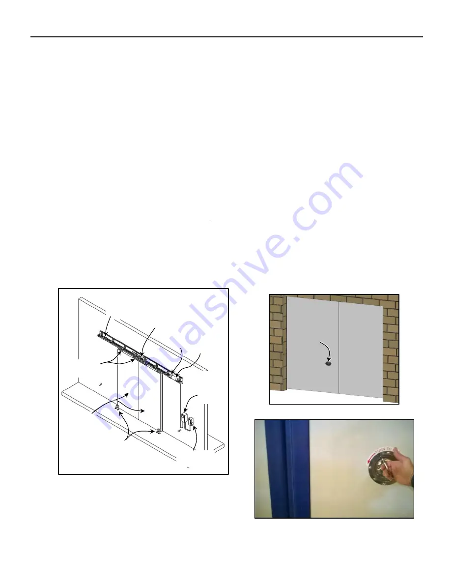
The power drive system for the Turbo Slide door
consists of a motor, a gearbox, tensioners, and an
electric brake. The power drive system can be
mounted on either side of the head assembly. The
location of the drive system is determined at the time
the door is ordered from the manufacturer. Additional
drive components include idler gear assemblies, a
drive chain, chain reverser assembly (Bi-Parting
Door), and trolleys. (See Figure 6)
Figure 6
One end of the drive chain loop is connected to the
drive gear on the motor. The other end is connected
to the return idler-tensioner assembly that includes
an adjustable gear used to tension the drive chain.
The door panel(s) are connected to the drive chain
via the chain release mechanism and hang from
trolleys. The trolleys roll along tracks in the head
assembly to move the door panel(s) back and forth to
open and close the door.
On Bi-Parting Door systems, the drive chain moves
the door panels/trolleys toward each other to close
the door or away from each other to open the door by
passing through the chain reverser assembly in the
center of the door.
MANUAL OPERATION
When the motor is not operating the door, during a
power loss, or when routine maintenance calls for
power to be disconnected, the motor is automatically
locked in place by an electric brake on the motor
assembly that, in turn, locks the door.
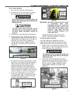
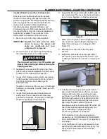
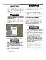
An electric brake is used to halt the door if power to
the door is shut off for any reason. A manual door
chain drive release assembly connected to a rotating
handle (via cable) is provided to release the door
from the drive chain allowing the door to be manually
opened and/or closed. During a power failure, when
routine maintenance calls for power to be
disconnected, or when needing to get through the
door from the rear/non-activated side, this manual
release handle can be used. (See Figures 7 and 8)
Figure 7
Figure 8
Insulated
Rytec Door
Panels
Drive
Pulley
Fused
Disconnect
Door Panel
Trolleys
Stay
Rollers
Bi-Parting Door Shown
One-Way Door Is Similar
Return Idler-
Tensioner
Assembly
Drive
Chain
Manual
Door Chain
Release
Handle
RYTEC
System 4
Control
Panel
Drive Motor/
Gearbox
Assembly
Содержание Turbo-Slide
Страница 2: ......
Страница 8: ......
Страница 29: ...21 NOTES...
Страница 32: ...PARTS LIST BI PARTING DOOR ASSEMBLY 24 BI PARTING DOOR ASSEMBLY Figure 48 1 2 3 4 6 7 8 9 10 Bi Parting Door 5...

