12
PLANNED MAINTENANCE
—QUARTERLY INSPECTION
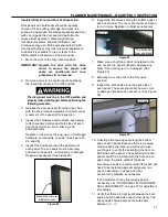
If adjustment is necessary, see “DOOR PANEL
ALIGNMENT AND ADJUSTMENT” on page 14 and
“DOOR RETENTION/BULB SEAL ADJUSTMENT”
on page 15.
12. Reconnect the door panel(s) to the drive chain.
13. Apply power and move the door to the fully
closed position.
IMPORTANT: Operate and cycle the door with the
drive motor to ensure the panels
and seals are positioned and com-
pressed as in normal use.
14. Confirm that the door is operating properly.
BI-PARTING DOOR CENTER SEAL INSPECTION
1. Move the door to the fully closed position.
2. Remove power to the control panel by placing
the fused disconnect in the OFF position.
The disconnect must be in the OFF position and
properly locked and tagged before performing the
following procedure.
3. Inspect the Bi-Parting door panel leading edge
seals. It should form a seal tight barrier along the
entire center vertical edge of the panels. They
are normal wear items and will need to be
replaced when worn to insure proper door seal
depending on usage and local environment.
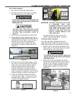
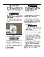
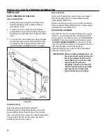
Replace or adjust as necessary. (See Figure 31)
Figure 31
4. Apply power to the control panel by placing the
fused disconnect in the ON position.
5. Restore power to the door and return to service.
If adjustment to the Bi-Parting panel leading edge
seal is necessary see “DOOR LEADING EDGE
SEAL ADJUSTMENT BI-
PARTING DOORS” on
page 17.
Cleaning Panels and Seals
Do not use an abrasive cleaner or a
petroleum-based solvent to clean the rollers
or the track they travel along, otherwise,
damage to the rollers could result.
1. Inspect the panels and seals for dirt and grime.
Clean as required using an all-purpose
household cleaner and a clean, soft cloth. Then
thoroughly rinse the panels and seals with fresh,
clean water.
2. Once the door is dry, apply power to the door.
3. Operate the door several times to verify that it
works properly.
Control Panel and Activator Inspection
1. Ensure all associated warning and safety labels
are intact, clean, and easy to read. Replace as
needed.
2. Check the control panel for proper operation.
Make any adjustments or repairs as necessary.
3. Operate the door five or six complete cycles with
each activator installed and used with the door. A
typical activator may be a floor loop, pull cord,
push button, motion detector, radio control, etc.
The open cycle is controlled by an activator. The
close cycle is controlled by an activator or by a
programmable timer internal to the control panel.
If a repair or adjustment is necessary, refer to the
operating instructions provided by the manufac-
turer of that particular activator. To set the auto-
matic timer, refer to the Rytec System 4 Drive &
Control Installation & Owner’s Manual.
Defrost System (Optional System)
HEAT TAPE INSPECTION
1. Remove power to the control panel by placing
the fused disconnect in the OFF position.
The disconnect must be in the OFF position and
properly locked and tagged before performing the
following procedure.
NOTE: The bi-parting door is shown. The one-way
door is the same.
Male Panel
Center Edge
Seal
Female Panel
Center Edge
Seal
Содержание Turbo-Slide
Страница 2: ......
Страница 8: ......
Страница 29: ...21 NOTES...
Страница 32: ...PARTS LIST BI PARTING DOOR ASSEMBLY 24 BI PARTING DOOR ASSEMBLY Figure 48 1 2 3 4 6 7 8 9 10 Bi Parting Door 5...


