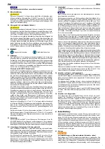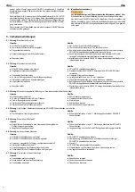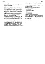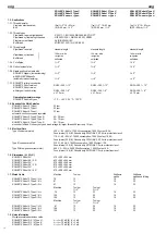
13
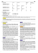
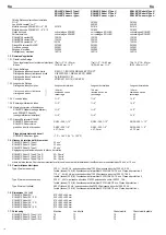
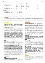
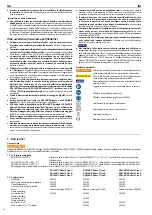
1.9. Vibrations (all types)
Weighted rms value of acceleration
< 2.5 m/s²
K = 1.5 m/s²
The indicated weighted effective value of acceleration has been measured against standard test procedures and can be used by way of comparison with another
device. The indicated weighted effective value of acceleration can also be used as a preliminary evaluation of the exposure.
CAUTION
CAUTION
The indicated weighted effective value of acceleration can differ during operation from the indicated value, dependent on the manner in which the device is used.
Dependent upon the actual conditions of use (periodic duty) it may be necessary to establish safety precautions for the protection of the operator.
2. Start-up
CAUTION
CAUTION
Transport weights above 35 kg must be carried by at least 2 persons, carry the
tool set separately. When transporting and installing the machine, please note
that the machine has a high centre of gravity with and without the base frame,
i.e. it is top heavy.
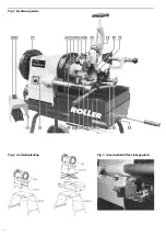
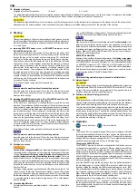
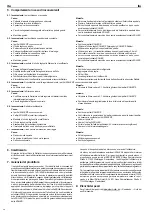
2.1. Installing ROLLER’S Robot 2U, 2K, 2D, ROLLER’S Robot 3U, 3K, 3D,
ROLLER’S Robot 4U, 4K, 4D
Remove both U-rails from the machine. Fix the machine to the oil tray. Push
the tool carrier into the guide arms. Push the pressing lever (8) from the rear
through the loop on the tool carrier and the clamping ring (10) onto the rear
guide arm so that the wing nut is facing the rear and the ring groove stays free.
Feed the hose with suction fi lter through the hole in the oil tray from the inside
and connect it to the coolant-lubricant pump. Push the other end of the hose
onto the nipple on the back of the tool carrier. Push the handle (9) onto the
pressing lever. Fix the machine to a workbench or subframe (accessory) with
the 3 screws provided. The machine can be lifted respectively at the front by
the guide arms and at the rear by a pipe clamped into a clamping and guide
chuck for transport. For transporting on the subframe, pipe sections Ø ¾" with
a length of approx. 60 cm are pushed into the eyes on the subframe and fi xed
with the wing nuts. If the machine is not to be transported, the two wheels can
be removed from the subframe.
Fill in 5 litres of thread cutting material. Insert chip tray.
NOTICE
NOTICE
Never operate the machine without thread cutting material.
Insert the guide bolt of the die head (12) into the hole of the tool carrier and
push on the die head with axial pressure on the guide pin and swivelling move-
ments as far as it will go.
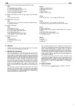
2.2. Installing ROLLER’S Robot 2U-L, 2K-L, 2D-L, ROLLER’S Robot 3U-L, 3K-L,
3D-L, ROLLER’S Robot 4U-L, 4K-L, 4D-L (Fig. 2)
Fix the machine to a workbench or subframe (accessory) with the 4 screws
provided. The machine can be lifted respectively at the front by the guide arms
and at the rear by a pipe clamped into a clamping and guide chuck for transport.
Push the tool carrier into the guide arms. Push the pressing lever (8) from the
rear through the loop on the tool carrier and the clamping ring (10) onto the
rear guide arm so that the wing nut is facing the rear and the ring groove stays
free. Push the handle (9) onto the pressing lever. Hang the oil tray in the two
screws on the gear housing and push to the right into the slits. Hang the oil
tray in the ring groove on the rear guide arm. Push on the clamping ring (10)
until it is touching the suspension of the oil tray and clamp it tight. Hang the
hose with suction fi lter into the oil tray and push the other end of the hose onto
the nipple on the back of the tool carrier.
Fill in 2 litres of thread cutting material. Insert the chip tray from the rear.
NOTICE
NOTICE
Never operate the machine without thread cutting material.
Insert the guide bolt of the die head (12) into the hole of the tool carrier and
push on the die head with axial pressure on the guide pin and swivelling move-
ments as far as it will go.
2.3. Electrical connection
WARNING
WARNING
Caution: Mains voltage present! Before connecting the thread cutting machine,
Caution: Mains voltage present!
Caution: Mains voltage present!
check whether the voltage given on the rating plate corresponds to the mains
voltage.
Only connect the thread cutting machine of protection class I to
a socket/extension lead with a functioning protective contact. There is a
danger of electric shock. On building sites, in a wet environment, indoors and
outdoors or under similar installation conditions, only operate the thread cutting
machine on the mains with a fault current protection switch (FI switch) which
interrupts the power supply as soon as the leakage current to earth exceeds
30 mA for 200 ms.
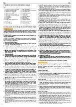
The thread cutting machine is switched on and off with the foot switch (4). The
switch (3) serves to pre-select the direction of rotation or speed. The machine
can only be switched on when the emergency off button (5) is unlocked and
the thermal protection switch (6) on the foot switch is pressed. If the machine
is connected directly to mains (without a plug device), a 16 A circuit breaker
must be installed.
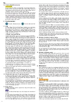
2.4. Thread-cutting Materials
For safety data sheets, see www.albert-roller.de → Downloads → Safety Data
Sheets.
Only use ROLLER thread cutting materials. They ensure perfect cutting results,
long life of the dies and considerably relieve stress on the tools.
NOTICE
NOTICE
ROLLER’S Smaragdol
High-alloy mineral oil-based thread-cutting material.
For all materials: steel,
stainless steel, non-ferrous metals, plastics. Can be washed out with water,
tested by experts. Mineral oil-based thread cutting materials are not approved
for drinking water pipes in different countries, e.g. Germany, Austria and Swit-
zerland. Mineral oil-free ROLLER’S Rubinol 2000 must be used in this case.
Observe the national regulations.
ROLLER’S Rubinol 2000
Mineral oil-free, synthetic thread-cutting material for
drinking water pipes.
Completely soluble in water. According to regulations. In Germany DVGW test
no. DW-0201AS2031, Austria ÖVGW test no. W 1.303, Switzerland SVGW test
no. 9009-2496. Viscosity at –10°C: ≤ 250 mPa s (cP). Pumpable up to –28°C.
Easy to use. Dyed red for checking washout. Observe the national regulations.
Both thread cutting materials are available in aerosol cans, canisters, barrels
as well as spray bottles (ROLLER’S Rubinol 2000).
NOTICE
NOTICE
All thread cutting materials may only be used in undiluted form!
2.5. Material Support
CAUTION
CAUTION
Pipes and bars longer than 2 m must be supported additionally by at least one
height-adjustable ROLLER’S Assistant 3B, ROLLER’S Assistant XL 12" mate-
rial rest. This has steel balls for easy movement of the pipes and bars in all
directions without the material support tipping over.
2.6. Subframe, mobile and folding (accessory)
CAUTION
CAUTION
The folded subframe, mobile and folding, quickly moves up automatically without
mounted thread cutting machine after releasing. Therefore hold down the subframe
by the handle when releasing and hold with both handles when moving up.
To move up with the thread cutting machine mounted, hold the subframe with
one hand on the handle, put one foot on the cross member and release both
locking pins by turning the lever. Then hold the subframe with both hands and
move to working height until the two locking pins snap in. Proceed in the reverse
order to fold up. Drain the thread-cutting material from the oil tray or remove
the oil tray before unfolding or folding up.
3. Operation
Use eye protection
Use ear protection
3.1. Tools
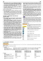
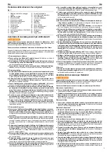
The die head (12) is a universal die head. That means for all types of threads
for above mentioned sizes, divided in 2 tool sets, only one die head is required.
For cutting tapered pipe threads, the length stop (13) needs to be in the same
direction with the closing and opening lever (14). To cut cylindrical long threads
and bolt threads, the length stop (13) has to be folded away.
Changing the ROLLER’S dies
The ROLLER’S dies can be inserted or changed with the die head mounted
on the machine or detached (i.e. on a bench). Slacken clamping lever (15) but
do not remove it. Push the adjusting disc (16) at the handle away from the
clamping lever to the far end position. In this position the ROLLER’S dies are
put in or taken out. Ensure that the indicated size of thread shown on the back
of the ROLLER’S dies corresponds to the size of thread to be cut. Furthermore,
ensure that the numbers shown on the back of the ROLLER’S dies correspond
with those indicated on the die holder (17).
Insert the ROLLER’S dies into the die head as far as the ball inside the slot of
the die holder snaps in. Once all ROLLER’S dies are set, adjust the size of
thread by shifting the adjusting disc. Bolt thread must always be set to „Bolt“.
Clamp the adjusting disc with the clamping lever, close the die head by pressing
the closing and opening lever (14) down slightly to the right. The die head opens
either automatically (with tapered pipe threads), or at any time manually by
slight pressure to the left on the closing and opening lever.
If the holding power of the clamping lever (15) is insuffi cient (e.g. through blunt
ROLLER’S dies) when the 2½ – 3" and the 2½ – 4" die head is in use, due to
the increased cutting force applied, with the result that the die head opens
under cutting pressure, the capscrew on the side opposite the clamping lever
(15) must also be tightened.
eng eng

