235
Appendices
●
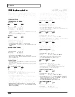
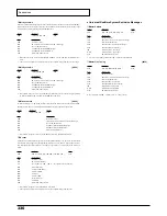
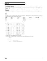
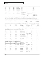
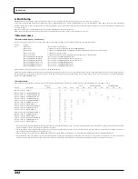
System Parameters
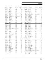
Parameters affecting the entire unit, such as how the two MIDI IN connectors will function, are called System Parameters.
<MODEL ID = 42H>
Address(H)
Size(H)
Data(H)
Parameter
Description Default(H)
Description
00 00 7F
00 00 01
00 – 01
SYSTEM MODE SET
00
MODE-1
00: MODE-1 (Single module mode)
(Rx. only)
*
When the Data value 00 is received, the same processing will be carried out as when GS Reset is received. Other values are ignored.
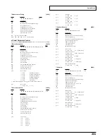
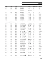
CHANNEL MSG RX PORT
00 01 00
00 00 01
00 – 03
BLOCK00
PORT A – D
00
PORT A
:
:
:
:
:
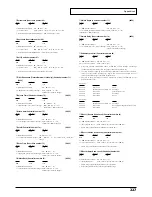
00 01 0F
00 00 01
00 – 03
BLOCK0F
PORT A – D
00
PORT A
00 01 10
00 00 01
00 – 03
BLOCK10
PORT A – D
01
PORT B
:
:
:
:
:
00 01 1F
00 00 01
00 – 03
BLOCK1F
PORT A – D
01
PORT B
00 01 20
00 00 01
00 – 03
BLOCK20
PORT A – D
02
PORT C [8850]
:
:
:
:
:
00 01 2F
00 00 01
00 – 03
BLOCK2F
PORT A – D
02
PORT C [8850]
00 01 30
00 00 01
00 – 03
BLOCK30
PORT A – D
03
PORT D [8850]
:
:
:
:
:
00 01 3F
00 00 01
00 – 03
BLOCK3F
PORT A – D
03
PORT D [8850]
*
You can modify the receiving MIDI port at which channel messages will be received for each BLOCK. We suggest that normally you use PORT A for BLOCK00 – 0F, PORT B for BLOCK10 –
1F, PORT C for BLOCK20 – 2F, and PORT D for BLOCK30 – 3F. (In this case there is no need to change the setting.)
*
Refer to page 237 for details of each BLOCK.
●
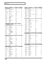
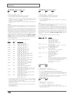
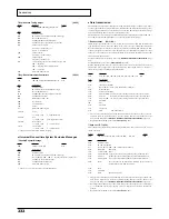
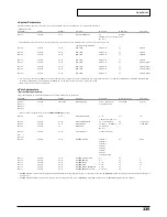
Patch parameters
❍
Patch common parameters
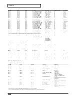
The parameters common to all Parts in each module are called Patch Common parameters.
Address(H)
Size(H)
Data(H)
Parameter
Description
Default Value (H)
Description
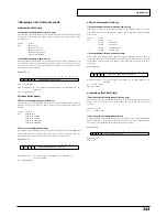
40 00 00
00 00 04
0018 – 07E8
MASTER TUNE
-100.0 – +100.0 [cents]
00 04 00 00
0 [cents]
40 00 01#
Use nibblized data.
40 00 02#
40 00 03#
*
Refer to section 5. Supplementary material,
About the Tuning
(page 245).
40 00 04
00 00 01
00 – 7F
MASTER VOLUME
0 – 127
7F
127
(= F0 7F 7F 04 01 00 vv F7)
40 00 05
00 00 01
28 – 58
MASTER KEY-SHIFT
-24 – +24 [semitones]
40
0 [semitones]
40 00 06
00 00 01
01 – 7F
MASTER PAN
-63 (LEFT) – +63 (RIGHT)
40
0 (CENTER)
40 00 7F
00 00 01
00
MODE SET
00 = GS Reset
(Rx. only)
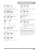
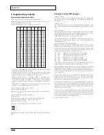
40 01 00
00 00 10
20 – 7F
PATCH NAME
16 ASCII Characters
40 01 : #
40 01 0F#
40 01 30
00 00 01
00 – 07
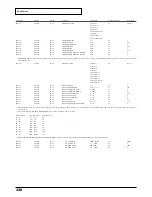
REVERB MACRO
00: Room 1
04
Hall 2
01: Room 2
02: Room 3
03: Hall 1
04: Hall 2
05: Plate
06: Delay
07: Panning Delay
40 01 31
00 00 01
00 – 07
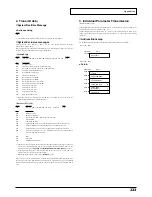
REVERB CHARACTER
0 – 7
04
4
40 01 32
00 00 01
00 – 07
REVERB PRE-LPF
0 – 7
00
0
40 01 33
00 00 01
00 – 7F
REVERB LEVEL
0 – 127
40
64
40 01 34
00 00 01
00 – 7F
REVERB TIME
0 – 127
40
64
40 01 35
00 00 01
00 – 7F
REVERB DELAY FEEDBACK
0 – 127
00
0
40 01 37
00 00 01
00 – 7F
REVERB PREDELAY TIME
0 – 127 [ms]
00
0
*
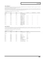
REVERB MACRO is a macro parameter that allows global setting of reverb parameters. When you select the reverb type with REVERB MACRO, each reverb parameter will be set to their most
suitable value.
*
REVERB CHARACTER is a parameter that changes the reverb algorithm. The value of REVERB CHARACTER corresponds to the REVERB MACRO of the same number.
Содержание Sound Canvas SC-8850
Страница 256: ...SC 8850 Owner s Manual 01891545 00 7 A3 31N...

