Rockwell Automation 2080-L50E-24AWB Скачать руководство пользователя страница 103

Rockwell Automation Publication 2080-UM002N-EN-E - November 2022

103

Chapter 6          Micro870 Controller Distributed Network Protocol

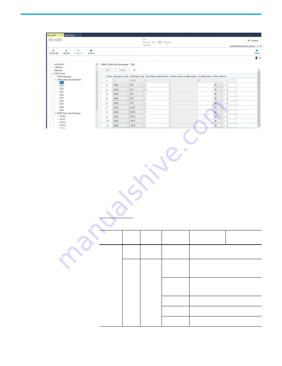
Descriptor Element Configuration: Each Descriptors element is configured by clicking on the 

individual DSX under the DNP3 Data-set Descriptor. Add new index by clicking Add in each DSX.

Descriptor Code: NAME, DAEL, PTYP

Data Type Code: VSTR, UINT, INT, FLT, OSTR, BSTR, TIME

Max Data Length (bytes): 0…255

Ancillary Value: Any string. This can be a binary array or ASCII string, up to 32 bytes.

Point Addressing under Descriptor Element Configuration: Data-Set value for each Data-Set 

element is configured by:

• Point Address Type
• Point Index

When these values are configured properly according to the supported data files, the 

controller responds with a Group 87, Variation 1 object filled with the value in the data file. 

Table 9 on page 103

 shows the supported data files for the Point Addressing.

Table 9 - Point Address Type — Standard DNP3 Point

Point Address 

Type

Data Type 

Code

Maximum 

Data Length 

(bytes)

Point Type

Point Index Low Byte Point Index High Byte

Standard

DNP3 Point

NONE = 0 0

NONE = 0: 

No point type is 

associated.

0

NONE = 0

UINT = 2

INT = 3

OSTR = 5

BSTR = 6

TIME = 7

0

0, 1, 2, or 4

0, 1, 2, or 4

0…255

0…255

0…6

BI = 1: 

Binary input

0…4095 max

When the Data Types other than OSTR and BSTR 

are used, the Point Index must be set to a point 

offset that is divisible by 16.

B2I = 3:

Double-bit input

0…2047 max

When the Data Types other than OSTR and BSTR 

are used, the Point Index must be set to a point 

offset that is divisible by 8.

CI = 20:

Counter

0…511 max

AI = 30:

Analog input

0…767 max

BCD = 101: 

BCD point

0…255 max

Содержание 2080-L50E-24AWB

Страница 1: ...Catalog Numbers 2080 LC50 24AWB 2080 L50E 24AWB 2080 LC50 24QWB 2080 L50E 24QWB 2080 LC50 24QVB 2080 L50E 24QVB 2080 LC50 24QBB 2080 L50E 24QBB 2080 LC50 48AWB 2080 L50E 48AWB 2080 LC50 48QWB 2080 L50E 48QWB 2080 LC50 48QWBK 2080 L50E 48QWBK 2080 LC50 48QVB 2080 L50E 48QVB 2080 LC50 48QBB 2080 L50E 48QBB Micro870 Controller Catalog Numbers 2080 LC70 24AWB 2080 L70E 24AWB 2080 LC70 24QWB 2080 L70E ...

Страница 2: ...oftware described in this manual Reproduction of the contents of this manual in whole or in part without written permission of Rockwell Automation Inc is prohibited Throughout this manual when necessary we use notes to make you aware of safety considerations These labels may also be on or inside the equipment to provide specific precautions The following icon may appear in the text of this documen...

Страница 3: ...3 Obtain Connected Components Workbench Software 23 Use Connected Components Workbench Software 23 Controller Changes in Run Mode 23 Using Run Mode Change RMC 23 Uncommitted Changes 25 RMC Memory 25 Limitations of RMC 27 Using Run Mode Configuration Change RMCC 27 Using Modbus RTU Communication 28 Using EtherNet IP Communication 30 Safety Considerations 31 Disconnect Main Power 31 Safety Circuits ...

Страница 4: ...ls 50 Grounding Your Analog Cable 51 Wiring Examples 51 Embedded Serial Port Wiring 52 Chapter 5 Communication Connections Overview 55 Supported Communication Protocols 55 Modbus RTU 56 CIP Serial Client Server DF1 57 ASCII 57 Modbus TCP Client Server 57 CIP Symbolic Client Server 57 CIP Client Messaging 58 Sockets Client Server TCP UDP 59 CIP Communications Pass thru 59 Examples of Supported Arch...

Страница 5: ...ice Attribute Object 106 Event Reporting 108 Generate Events 108 DNP3 10K Event Logging 110 Control Generating Event 110 Report Event By Polled Response 111 Report Event By Unsolicited Response 111 Collision Avoidance 112 Time Synchronization 113 Diagnostics 114 Diagnostics for Ethernet Channel 115 Diagnostics for Secure Authentication 116 Function Codes 116 Implementation Table 117 Chapter 7 Prog...

Страница 6: ...apter 9 Motion Control PTO Motion Control 157 Use the Micro800 Motion Control Feature 158 Input and Output Signals 159 Motion Control Function Blocks 162 General Rules for the Motion Control Function Blocks 163 Motion Axis and Parameters 170 Axis States 171 Limits 172 Motion Stop 174 Motion Direction 175 Axis Elements and Data Types 175 Axis Error Scenarios 176 MC_Engine_Diag Data Type 177 Functio...

Страница 7: ...guration 220 HSC Interrupt POU 221 HSC Interrupt Status Information 222 Chapter 11 Controller Security Protected Mode 225 Exclusive Access 225 Password Protection 225 Compatibility 226 Work with a Locked Controller 227 Upload from a Password Protected Controller 227 Debug a Password Protected Controller 227 Download to a Password Protected Controller 227 Transfer Controller Program and Password Pr...

Страница 8: ...Linx and a Micro830 Micro850 Micro870 Controller through USB 272 Configure Controller Password 276 Set Controller Password 276 Change Password 277 Clear Password 278 Use the High Speed Counter 279 Create the HSC Project and Variables 280 Assign Values to the HSC Variables 283 Assign Variables to the Function Block 285 Run the High Speed Counter 286 Use the Programmable Limit Switch PLS Function 28...

Страница 9: ... a Fault Log 314 Controller Error Recovery Model 315 Ethernet Diagnostics 316 General Diagnostic Information 317 EtherNet IP Overview Diagnostic Information 319 System Diagnostic Information 321 Controller Diagnostic Information 322 Calling Rockwell Automation for Assistance 322 Appendix E PID Function Blocks PID Function Block 324 IPIDCONTROLLER Function Block 326 How to Autotune 328 How Autotune...

Страница 10: ...mmunication Diagnostics 347 Configure a Radio Modem Station 348 DF1 Radio Modem Communication Diagnostics 349 Configure the Store and Forward Table 350 Appendix H User defined Function Block Motion Instructions PowerFlex 520 series User defined Function Block Details 353 Kinetix 5100 Drive Device Object UDFB 355 Configure UDFBs for Kinetix 5100 Drives 357 raC_Dvc_K5100 357 raC_UDT_Itf_K5100_Cfg 35...

Страница 11: ...release notes from the Product Compatibility and Download Center at rok auto pcdc Summary of Changes This publication contains the following new or updated information This list includes substantive updates only and is not intended to reflect all changes Additional Resources These documents contain additional information concerning related products from Rockwell Automation You can view or download...

Страница 12: ...ng and wiring the expansion I O modules 2085 IF4 2085 IF8 2085 OF4 Micro800 4 channel Thermocouple RTD Input Module Installation Instructions publication 2085 IN007 Information on mounting and wiring the expansion I O module 2085 IRT4 Micro870 Programmable Controllers 24V DC Expansion Power Supply Installation Instructions publication 2085 IN008 Information on mounting and wiring the optional exte...

Страница 13: ...ance of Solid state Control publication SGI 1 1 Designed to harmonize with NEMA Standards Publication No ICS 1 1 1987 and provides general guidelines for the application installation and maintenance of solid state control in the form of individual devices or packaged assemblies incorporating solid state components Industrial Automation Wiring and Grounding Guidelines publication 1770 4 1 Provides ...

Страница 14: ...14 Rockwell Automation Publication 2080 UM002N EN E November 2022 Notes ...

Страница 15: ...ter provides an overview of the Micro830 Micro850 and Micro870 controller hardware features It has the following topics Topic Page Hardware Features 16 Micro830 Controllers 16 Micro850 Controllers 17 Micro870 Controllers 19 Programming Cables 21 Embedded Serial Port Cables 21 Embedded Ethernet Support 22 ...

Страница 16: ...ny class 2 rated 24V DC output power supply that meets minimum specifications such as the optional Micro800 power supply See Troubleshooting on page 307 for descriptions of status indicator operation for troubleshooting purposes Micro830 Controllers IMPORTANT For information on supported plug in modules and expansion I O see the following publications Micro800 Expansion I O Modules User Manual pub...

Страница 17: ...Removable I O terminal block 13 Optional AC power supply 7 Right side cover Status Indicator Description 1 1 For detailed description of the different status LED indicators see Troubleshooting on page 307 Description Description 14 Input status 18 Force status 15 Power status 19 Serial communications status 16 Run status 20 Output status 17 Fault status 14 15 16 17 18 19 20 1 2 12 11 10 13 6 9 8 3...

Страница 18: ...ndicators see Troubleshooting on page 307 Description Description 16 Input status 21 Fault status 17 Module Status 22 Force status 18 Network Status 23 Serial communications status 19 Power status 24 Output status 20 Run status Controller Description Description Description 1 Status indicators 9 Expansion I O slot cover 2 Optional power supply slot 10 DIN rail mounting latch 3 Plug in latch 11 Mod...

Страница 19: ...2 Optional power supply slot 10 DIN rail mounting latch 3 Plug in latch 11 Mode switch 4 Plug in screw hole 12 Type B connector USB port 5 40 pin high speed plug in connector 13 RS 232 RS 485 non isolated combo serial port 6 Removable I O terminal block 14 RJ 45 Ethernet connector with embedded green and yellow LED indicators 7 Right side cover 15 Optional power supply 8 Mounting screw hole mounti...

Страница 20: ...4QBB 14 10 2 4 2080 LC30 48AWB 28 20 2080 LC30 48QWB 28 20 6 2080 LC30 48QVB 28 20 3 6 2080 LC30 48QBB 28 20 3 6 Table 2 Micro850 Controllers Number and Types of Inputs Outputs Catalog Number Inputs Outputs PTO Support HSC Support 120V AC 24V DC V AC Relay 24V Sink 24V Source 2080 LC50 24AWB 14 10 2080 L50E 24AWB 14 10 2080 LC50 24QWB 14 10 4 2080 L50E 24QWB 14 10 4 2080 LC50 24QVB 14 10 2 4 2080 ...

Страница 21: ...2080 L70E 24QWB 14 10 4 2080 LC70 24QWBK 14 10 4 2080 L70E 24QWBK 14 10 4 2080 L70E 24QWBN 14 10 4 2080 LC70 24QBB 14 10 2 4 2080 L70E 24QBB 14 10 2 4 2080 LC70 24QBBK 14 10 2 4 2080 L70E 24QBBK 14 10 2 4 2080 L70E 24QBBN 14 10 2 4 Table 4 Embedded Serial Port Cable Selection Chart Connectors Length Cat No Connectors Length Cat No 8 pin Mini DIN to 8 pin Mini DIN 0 5 m 1 5 ft 1761 CBL AM00 1 8 pin...

Страница 22: ...Indication Micro850 and Micro870 controllers also support two LEDs for EtherNet IP to indicate the following Module status Network status See Troubleshooting on page 307 for descriptions of Module and Network status indicators Yellow LED Green LED RJ 45 connector RJ 45 Ethernet Port Pin Mapping Contact Number Signal Direction Primary Function 1 TX OUT Transmit data 2 TX OUT Transmit data 3 RX IN D...

Страница 23: ...elp it comes with the software Controller Changes in Run Mode Micro820 Micro830 Micro850 Micro870 controllers allow you to make certain changes while in run mode by using the following features Run Mode Change RMC This feature allows logic modifications to a running project without going to remote program mode For more information see Using Run Mode Change RMC on page 23 Run Mode Configuration Cha...

Страница 24: ...er after performing Run Mode Change do a full build and try to reconnect Connected Components Workbench software treats the project in the controller as different from the project in Connected Components Workbench software and ask to either upload or download even though the logic is identical Example of the Benefits of Using RMC 20 Reduction in Download Time Number of Changes Time to Perform Conv...

Страница 25: ... user variables changes per Test Logic To adjust the amount of RMC memory the controller must be offline After you have adjusted the amount you must build the project and download it to the controller Controller Memory Diagnostics Page in Connected Components Workbench Software During RMC an incremental build is performed and only incremental changes are downloaded to the controller until the RMC ...

Страница 26: ...ll build and download while the controller is disconnected RMC Memory Usage When Performing Full Build and Download Example However if the controller memory does not have enough space remaining to copy the contents of the RMC memory as shown below the operation will fail and a not enough memory error message will appear Do not use RMC if you are near the limits of your controller memory Insufficie...

Страница 27: ...re must be disconnected from the controller When using CIP messaging in RMC setting the CIPTARGETCFG data type parameter ConnClose to TRUE has no effect The Ethernet session does not close immediately upon successful messaging and you have to wait for the connection to timeout after 60 seconds This applies to Connected Components Workbench software version 9 or earlier projects For version 10 or l...

Страница 28: ...trollers the address configuration change is permanent and will retained when the controller is power cycled From firmware revision 10 onwards Micro820 controllers also retain the address configuration when the controller is power cycled Using Modbus RTU Communication To use RMCC with the Modbus RTU communication protocol the serial port must be set to the Modbus slave role A CIP Generic message i...

Страница 29: ... be 1 this indicates that the Modbus role is configured as Slave RMCC Modbus Example Set the Message Length When the new node address is configured and applied the port is not restarted You can verify that the node address has changed after performing RMCC by looking at the Communication Diagnostics tab for the controller RMCC Modbus Example Verify Address Change IMPORTANT You must ensure that the...

Страница 30: ...lowing parameters Use RMCC when configuring the controller during commissioning Immediately after changing the IP address the cycle time may increase up to 100 ms for one program scan RMCC EtherNet IP Example Set the Parameters RMCC EtherNet IP Example Set the New IP Address For this example the new IP Address is set to the following IP address 192 168 1 10 Subnet mask 255 255 255 0 Gateway addres...

Страница 31: ... of your equipment is of primary importance We recommend reviewing the following safety considerations Disconnect Main Power The main power disconnect switch should be located where operators and maintenance personnel have quick and easy access to it In addition to disconnecting electrical power all other sources of power pneumatic and hydraulic should be de energized before working on a machine o...

Страница 32: ...ol relay circuit The failure of one of these switches would most likely cause an open circuit which would be a safe power off failure However if one of these switches shorts out it no longer provides any safety protection These switches should be tested periodically to assure they will stop machine motion when needed Power Considerations The following explains power considerations for the micro co...

Страница 33: ...pted It is also possible that the voltage level may drop substantially below the normal line voltage range for a period of time Both of these conditions are considered to be a loss of power for the system Preventing Excessive Heat For most applications normal convective cooling keeps the controller within the specified operating range Ensure that the specified temperature range is maintained Prope...

Страница 34: ...ency stop switch should turn off all machine power by turning off the master control relay Observe all applicable local codes concerning the placement and labeling of emergency stop switches Install emergency stop switches and the master control relay in your system Make certain that relay contacts have a sufficient rating for your application Emergency stop switches must be easy to reach In the f...

Страница 35: ...ntacts will remove power from the external I O circuits stopping machine motion Fuse Overtravel limit switch MCR MCR MCR Stop Start Line terminals Connect to terminals of power supply 115V AC or 230V AC I O circuits L1 L2 230V AC Master Control Relay MCR Cat No 700 PK400A1 Suppressor Cat No 700 N24 MCR Suppr 24V DC I O circuits Lo Hi DC power supply Use IEC 950 EN 60950 X1 X2 115V AC or 230V AC Li...

Страница 36: ...ping machine motion Fuse MCR Fuse MCR MCR MCR Stop Start Line terminals Connect to terminals of power supply Line terminals Connect to 24V DC terminals of power supply 230V AC output circuits Disconnect Isolation transformer 115V AC or 230V AC I O circuits L1 L2 Master Control Relay MCR Cat No 700 PK400A1 Suppressor Cat No 700 N24 Lo Hi DC power supply Use NEC Class 2 for UL Listing X1 X2 115V AC ...

Страница 37: ...dimensions do not include mounting feet or DIN rail latches Micro830 10 point and 16 point Controllers 2080 LC30 10QWB 2080 LC30 10QVB 2080 LC30 16AWB 2080 LC30 16QWB 2080 LC30 16QVB Micro830 24 point Controllers 2080 LC30 24QW8B 2080 LC30 24QVB 2080 LC30 24QBB Topic Page Controller Mounting Dimensions 37 Mounting Dimensions 37 DIN Rail Mounting 39 Panel Mounting 39 100 3 94 80 3 15 90 3 54 Measur...

Страница 38: ...B 2080 L70E 24QBBK 2080 L70E 24QBBN Micro850 48 point Controllers 2080 LC50 48AWB 2080 LC50 48QWB 2080 LC50 48QWBK 2080 LC50 48QBB 2080 LC50 48QVB 2080 L50E 48AWB 2080 L50E 48QWB 2080 L50E 48QWBK 2080 L50E 48QBB 2080 L50E 48QVB Maintain spacing from objects such as enclosure walls wireways and adjacent equipment Allow 50 8 mm 2 in of space on all sides for adequate ventilation If optional accessor...

Страница 39: ...preferred mounting method is to use four M4 8 screws per module Hole spacing tolerance 0 4 mm 0 016 in Follow these steps to install your controller using mounting screws 1 Place the controller against the panel where you are mounting it Make sure the controller is spaced properly 2 Mark drilling holes through the mounting screw holes and mounting feet then remove the controller 3 Drill the holes ...

Страница 40: ...lers 2080 LC70 24AWB 2080 LC70 24QWB 2080 LC70 24QWBK 2080 LC70 24QBB 2080 LC70 24QBBK 2080 L70E 24AWB 2080 L70E 24QWB 2080 L70E 24QWBK 2080 L70E 24QWBN 2080 L70E 24QBB 2080 L70E 24QBBK 2080 L70E 24QBBN Micro830 48 Point Controllers 2080 LC30 48AWB 2080 LC30 48QWB 2080 LC30 48QVB 2080 LC30 48QBB Micro850 48 point Controllers 2080 LC50 48AWB 2080 LC50 48QWB 2080 LC50 48QWBK 2080 LC50 48QBB 2080 LC5...

Страница 41: ...131 5 16 22 8 0 90 36 6 1 44 90 100 110 8 4 36 33 8 1 33 7 2 0 28 3 94 3 54 Expansion I O slots Applicable to Micro850 and Micro870 only Single width 1st slot Double width 2nd slot 2085 ECR terminator Micro830 Micro850 Micro870 24 pt controller with Micro800 power supply Measurements in mm in 80 3 15 87 3 42 Expansion I O Slots Applicable to Micro850 and Micro870 only Single width 1st slot Double ...

Страница 42: ...4 1 75 14 4 0 57 216 8 50 7 0 27 22 8 0 90 36 6 1 44 90 100 1 110 8 4 36 3 94 3 54 Expansion I O Slots Applicable to Micro850 only Single width 1st slot Double width 2nd slot 2085 ECR terminator Micro830 Micro850 48 pt Controller with Micro800 Power Supply Measurements in mm in 80 3 15 87 3 42 Expansion I O Slots Applicable to Micro850 only Single width 1st slot Double width 2nd slot 2085 ECR term...

Страница 43: ... DC wiring and red for AC wiring Topic Page Wiring Requirements and Recommendation 43 Use Surge Suppressors 44 Recommended Surge Suppressors 45 Grounding the Controller 46 Wiring Diagrams 46 Controller I O Wiring 50 Minimize Electrical Noise 50 Analog Channel Wiring Guidelines 50 Minimize Electrical Noise on Analog Channels 50 Grounding Your Analog Cable 51 Wiring Examples 51 Embedded Serial Port ...

Страница 44: ...04 diode for surge suppression as shown in Figure 4 For inductive DC load devices a diode is suitable A 1N4004 diode is acceptable for most applications A surge suppressor can also be used See Recommended Surge Suppressors on page 45 These surge suppression circuits connect directly across the load device Figure 4 DC Outputs with Surge Suppression Suitable surge suppression methods for inductive A...

Страница 45: ... 1 MOV 56 136V AC 78 180V DC 100 FSV136 1 137 277V AC 181 250V DC 100 FSV277 1 278 575V AC 100 FSV575 1 12 250V DC 100 FSD250 1 Diode Bulletin 509 Motor Starter Size 0 5 12 120V AC 599 K04 MOV 240 264V AC 599 KA04 Bulletin 509 Motor Starter Size 6 12 120V AC 199 FSMA1 3 RC 12 120V AC 199 GSMA1 4 MOV Bulletin 700 R RM Relay AC coil Not Required 24 48V DC 199 FSMA9 MOV 50 120V DC 199 FSMA10 130 250V...

Страница 46: ...nnected to the RS 232 RS 485 communication port must be referenced to controller ground or be floating not referenced to a potential other than ground Failure to follow this procedure may result in property damage or personal injury 2080 LC30 16AWB has no high speed inputs I 00 COM0 I 01 I 02 I 03 COM1 I 04 I 05 NC NC NC NC 1 2 3 4 5 6 7 8 9 10 11 12 DC24 CM0 O 00 DC24 CM1 O 01 CM2 O 02 O 03 CM3 N...

Страница 47: ...DC24 CM1 O 01 CM2 O 02 O 04 O 03 CM3 O 05 1 2 3 4 5 6 7 8 9 10 11 12 I 11 I 10 I 13 I 12 13 14 15 16 O 07 O 06 O 09 O 08 13 14 15 16 Input terminal block Output terminal block I 00 COM0 I 01 I 02 I 03 I 04 I 05 I 06 COM1 I 07 I 09 I 08 1 2 3 4 5 6 7 8 9 10 11 12 DC24 CM0 O 00 DC24 CM1 O 01 CM2 O 02 O 04 O 03 CM3 O 05 1 2 3 4 5 6 7 8 9 10 11 12 I 11 I 10 I 13 I 12 13 14 15 16 O 07 O 06 O 09 O 08 13...

Страница 48: ... 15 16 O 07 O 06 O 09 O 08 13 14 15 16 24 VDC 24 VDC N L L1 L2 2080 PS120 240VAC L2 a DC c CR CR CR CR DC c L2 c L1 c L1 b DC c CR DC c L2 b L1 a L2 b L1 b IMPORTANT Do not connect DC24 Output terminal 2 to Earth Chassis Ground I 00 COM0 I 01 I 02 I 03 I 04 I 05 I 06 COM1 I 07 I 09 I 08 1 2 3 4 5 6 7 8 9 10 11 12 DC24 CM0 O 00 DC24 O 01 CM0 CM1 O 02 O 04 O 03 O 06 O 05 1 2 3 4 5 6 7 8 9 10 11 12 I...

Страница 49: ...O 02 O 04 O 03 O 06 O 05 1 2 3 4 5 6 7 8 9 10 11 12 I 11 I 10 I 13 I 12 13 14 15 16 O 08 O 07 CM1 O 09 13 14 15 16 24 VDC 24 VDC N L L1 L2 2080 PS120 240VAC DC d CR CR Sourcing DC b Sinking DC b Sourcing DC b Sinking DC b Sourcing DC a Sinking DC a Sourcing DC a Sinking DC a DC e DC e DC d IMPORTANT Do not connect DC24 Output terminal 2 to Earth Chassis Ground 2080 LC30 48AWB has no high speed inp...

Страница 50: ...ch other Use Belden cable 8761 or equivalent shielded wire Under normal conditions the drain wire shield should be connected to the metal mounting panel earth ground Keep the shield connection to earth ground as short as possible To ensure optimum accuracy for voltage type inputs limit overall cable impedance by keeping all analog cables as short as possible Locate the I O system as close to your ...

Страница 51: ...AC wiring Additional noise immunity can be obtained by routing the cables in grounded conduit Grounding Your Analog Cable Use shielded communication cable Belden 8761 The Belden cable has two signal wires black and clear one drain wire and a foil shield The drain wire and foil shield must be grounded at one end of the cable Wiring Examples Examples of sink source input output wiring are shown belo...

Страница 52: ...ini DIN connector For example the 1761 CBL PM02 cable is typically used to connect the embedded serial port to PanelView 800 HMI using RS 232 Embedded Serial Port D DC COM OUT V DC S G 24V supply Logic side User side Load Fuse Source output wiring example Micro800 source output Com Fuse 24V DC I P Source input wiring example Pinout Explanations Pin Definition RS 485 Example RS 232 Example 1 RS 485...

Страница 53: ... not connect the GND pin of the serial port to Earth Chassis Ground The GND pin of the serial port is the DC common for the Serial Port Communication signals and is not intended for Shield Ground If the length of the serial cable is more than 3 meters use an isolated serial port catalog number 2080 SERIALISOL ...

Страница 54: ...54 Rockwell Automation Publication 2080 UM002N EN E November 2022 Chapter 4 Wire Your Controller Notes ...

Страница 55: ...ication through the embedded RS 232 RS 485 serial port as well as any installed serial port plug in modules In addition Micro850 and Micro870 controllers also support communication through the embedded Ethernet port and can be connected to a local area network for various devices providing 10 Mbps 100 Mbps transfer rate These are the communication protocols supported by Micro830 Micro850 Micro870 ...

Страница 56: ... Help For more information about the Modbus protocol see Modbus Protocol Specifications available from https www modbus org For information on Modbus mapping see Modbus Mapping for Micro800 on page 261 To configure the serial port as Modbus RTU see Configure Modbus RTU on page 64 Connection Limits for Micro830 Micro850 Micro870 Controllers Description Micro830 Micro850 Micro870 CIP Connections Tot...

Страница 57: ...odbus Slave features on Ethernet No protocol configuration is required other than configuring the Modbus mapping table For information on Modbus mapping see Modbus Mapping for Micro800 on page 261 With Connected Components Workbench software version 12 or later the Modbus TCP Server is disabled by default If you want to use Modbus TCP you can enable it from the Ethernet settings CIP Symbolic Clien...

Страница 58: ...ed Array of strings are also supported CIP Client Messaging CIP Generic and CIP Symbolic messages are supported on Micro800 controllers through the Ethernet and serial ports These client messaging features are enabled by the MSG_CIPSYMBOLIC and MSG_CIPGENERIC function blocks For more information and sample quickstart project to help you use the CIP Client Messaging feature see Micro800 Programmabl...

Страница 59: ...Micro830 Micro850 and Micro870 controllers support a maximum of one hop A hop is defined to be an intermediate connection or communications link between two devices in Micro800 this is through EtherNet IP or CIP Serial or CIP USB Examples of Supported Architectures USB to EtherNet IP EtherNet IP to CIP Serial USB to DeviceNet Micro850 controller1 USB Micro850 controller2 Micro850 controller3 Ether...

Страница 60: ...h is 15 24 m 50 ft with a 25 pin or 9 pin connector See the following typical pinout for constructing a straight through cable Configure Serial Port You can configure the serial port driver as CIP Serial Modbus RTU ASCII or Shutdown through the Device Configuration tree in the Connected Components Workbench software DeviceNet PowerFlex 525 drive with 25 COMM D adapter Address 1 EtherNet IP Esc Sel...

Страница 61: ...Click Serial Port 2 Select CIP Serial from the Driver field 3 Specify a baud rate Select a communication rate that all devices in your system support Configure all devices in the system for the same communication rate Default baud rate is set at 38 400 bps 4 In most cases parity and station address should be left at default settings 5 Click Advanced Settings and set Advanced parameters See Table 5...

Страница 62: ...ecause the controller received a NAK response to the previous message packet transmission 3 ENQ Retries The number of enquiries ENQs that you want the controller to send after an ACK timeout occurs 3 Transmit Retries Specifies the number of times a message is retried after the first attempt before being declared undeliverable Enter a value from 0 127 3 ACK Timeout x20 ms Specifies the amount of ti...

Страница 63: ... MESSAGE TRANSFER PER NODE SCAN Choose this method only if it is critical to keep the poll list scan time to a minimum Receive as many messages from a slave station as it has choose STANDARD MULTIPLE MESSAGE TRANSFER PER NODE SCAN Accept unsolicited messages from slave stations choose MESSAGE BASED ALLOW SLAVES TO INITIATE MESSAGES Slave station initiated messages are acknowledged and processed af...

Страница 64: ...On the device configuration tree go to the Controller properties Click Serial Port 2 Select Modbus RTU on the Driver field 3 Specify the following parameters Baud rate Parity Unit address Modbus Role Master Slave Auto Modbus RTU Parameters Parameter Options Default Baud Rate 1200 2400 4800 9600 19200 38400 19200 Parity None Odd Even None Modbus Role Master Slave Auto Master ...

Страница 65: ...es Click Serial Port 2 Select ASCII on the Driver field 3 Specify baud rate and parity Modbus RTU Advanced Parameters Parameter Options Default Media RS 232 RS 232 RTS CTS RS 485 RS 232 Data Bits Always 8 8 Stop Bits 1 2 1 Response Timer 0 999 999 999 milliseconds 200 Broadcast Pause 0 999 999 999 milliseconds 200 Inter char Timeout 0 999 999 999 microseconds 0 RTS Pre delay 0 999 999 999 microsec...

Страница 66: ...ess automatically using DHCP or manually configure IP address subnet mask and gateway address ASCII Advanced Parameters Parameters Options Default Control Line Full Duplex Half duplex with continuous carrier Half duplex without continuous carrier No Handshake No Handshake Deletion Mode CRT Ignore Printer Ignore Data Bits 7 8 8 Stop Bits 1 2 1 XON XOFF Enabled or Disabled Disabled Echo Mode Enabled...

Страница 67: ...dule cannot be set to zero a multicast address a broadcast address or an address on the Class A loopback network 127 x x x The IP address should not start with zero and the IP address network ID should be not zero The Network mask cannot be set to 255 255 255 255 The Gateway address must be on the same subnet as the IP address that is being configured The Name Server address cannot be set to zero ...

Страница 68: ...s Workbench project On the device configuration tree go to the Controller properties Click Serial Port 2 Select CIP Serial from the Driver field 3 Specify a baud rate Select a communication rate that all devices in your system support Configure all devices in the system for the same communication rate Default baud rate is set 38 400 bps 4 In most cases parity and station address should be left at ...

Страница 69: ...col for the Ethernet channel in the controller is EtherNet IP To communicate with DNP3 over IP protocol select DNP3 over IP Enable in the Ethernet configuration page To program the controller use Connected Components Workbench software version 20 01 00 or later Topic Page Channel Configuration for DNP3 Slave 69 DNP3 Slave Application Layer 92 DNP3 Objects and Controller Variables 96 DNP3 Device At...

Страница 70: ...ch software open the Micro870 controller project tree There are three configurations related to DNP3 protocol in Connected Components Workbench software Serial and or Ethernet port configuration DNP3 Slave Application Layer configuration Serial Port Link Layer Configuration Link Layer related configuration can be done in the Serial Port configuration page ...

Страница 71: ... Chapter 6 Micro870 Controller Distributed Network Protocol Ethernet Layer Configuration To enable DNP3 over IP protocol select DNP3 over IP Enable in the Ethernet configuration page Link Layer related configuration can also be done in the Ethernet configuration page ...

Страница 72: ...figured for DNP3 protocol Any changes in the DNP3 Slave configuration page affects all ports Serial Link Layer Configuration Parameters Driver This selection should be set to DNP3 Slave to communicate with DNP3 protocol Node Address This value is a node address of this DNP3 Slave The valid range is 0 65519 Default value is 1 Baud The selections can be 38400 19200 9600 4800 2400 and 1200 Default se...

Страница 73: ...r Master Node0 This value is used to Validate the Master node address when the Enable Master Address Validation is Enabled Checked Vend Unsolicited Response when Unsolicited Response functionality is enabled An Unsolicited Response is sent out to the DNP3 Master having this address The valid range is 0 65519 Default value is 0 Master Node1 Master Node2 Master Node3 Master Node4 The valid range is ...

Страница 74: ...ive a confirmation frame until this timeout has expired The valid range is 1 65535 Default value is 20 Message Retries When Confirmation Timeout x1 ms has expired and this parameter was non zero value the controller tries to send retry packets The valid range is 0 255 Default value is 0 Pre transmit Delay x1 ms The controller waits for the specified time before sending the packet The valid range i...

Страница 75: ...ponses are transmitted via this connection The unsolicited responses are transmitted via this connection when this connection is available UDP datagram Accepts only broadcast packets when DNP3 destination node is one of 0xFFFD 0xFFFE and 0xFFFF in the request Dual End Point A single TCP server connection Any of the requests are accepted and the responses are transmitted via this connection The uns...

Страница 76: ...Node3 Master Node4 on page 73 The maximum number of Master Node Address for the Master Address Validation is 5 Enable Self Address The valid selections are Enabled Checked and Disabled Unchecked Default value is Disabled Unchecked When this bit is Disabled Unchecked any packets which contain the destination address 65532 FFFCh are ignored When this bit is Enabled Checked any packets which contain ...

Страница 77: ...Validation is Enabled Checked The valid range is 0 65519 Default value is 0 Master IP Address0 This value is used to Validate Master IP address when the Enable Access Control is Enabled Checked Send Unsolicited Response when Unsolicited Response functionality is enabled An Unsolicited Response is sent out to the DNP3 Master having this address The valid value is an IP address Default value is 0 0 ...

Страница 78: ...535 Default value is 20000 Keep Alive Interval x 1s This parameter specifies a time interval for TCP Keep Alive mechanism If the timer times out the controller transmits a keep alive message The keep alive message is a DNP Data Link Layer status request FC_REQUEST_LINK_STATUS If a response is not received to the keep alive message the controller deems the TCP connection broken and closes the TCP c...

Страница 79: ...ored after a power cycle Valid selections are Enabled Checked and Disabled Unchecked with disabled as default value Unsolicited Responses On Start Up Valid selections are Enabled Checked and Disabled Unchecked Default value is Disabled Unchecked When the selection is Disabled Unchecked the controller does not send any enabled Unsolicited Responses after a restart until it has received a FC_ENABLE_...

Страница 80: ...ted Null Response On Start Up Valid selections are Enabled Checked and Disabled Unchecked Default value is Disabled Unchecked When the selection is Disabled Unchecked the controller does not send Unsolicited NULL Response with RESTART IIN bit on startup When the selection is Enabled Checked the controller sends Unsolicited NULL Response with RESTART IIN bit on startup This selection is also used f...

Страница 81: ...turned on Max Response Size The controller sends Application Layer frame to fit in Max Response Size If the Response packet size is larger than this value the controller fragments the Response packet The valid range is 27 2048 in bytes Default value is 2048 Confirmation Timeout x1 ms When Enable Confirmation is enabled the controller waits for Application Layer Confirmation until the Confirmation ...

Страница 82: ... reaches this value an Unsolicited Response is initiated The valid range is 0 10000 Default value is 10 See DNP3 10K Event Logging on page 110 for more information Hold Time after Class2 Events x 1s This parameter is only for a Class 2 Unsolicited Response The controller holds the events during Hold Time after Class2 Events x 1s before initiating an Unsolicited Response The valid range is 0 65535 ...

Страница 83: ...Block and AOB Analog Output Block After receiving the request with the function code FC_SELECT 3 DNP3 Master should send the request with the function code FC_OPERATE 4 within this configured time DNP3 Object Data and Config The DNP3 Mapping selection under DNP3 Slave in the controller properties allow you to define the mapping of the listed DNP3 object and object properties class number online of...

Страница 84: ...Default value is Disabled Unchecked When the selection is Disabled Unchecked the controller disables DNP3 Aggressive Mode in Secure Authentication subsystem When the selection is Enabled Checked the controller enables DNP3 Aggressive Mode in Secure Authentication subsystem Critical Function Code in Secure Authentication This critical function code in the DNP3 Slave configuration page is used to de...

Страница 85: ... is used for configuring the reply timeout in 100 ms The valid range is 0 1200 120 s Default value is 20 2 s Maximum Error Count in Secure Authentication This parameter is used for configuring the maximum error count The valid range is 0 10 Default value is 2 HMAC Algorithm in Secure Authentication This parameter is used for configuring the HMAC Algorithm SHA 1 Truncated to 4 octets serial Truncat...

Страница 86: ...er User Name Define the unique name for each user up to 32 characters numbers alphabets and symbols Update Key The key to be used by each user up to 32 hexadecimal digits To create a new user follow these steps 1 Click Configure to open Update Key 2 Click Add 3 Enter the User Number select the User Role enter the User Name and enter the Update Key 4 Click Encrypt or OK to create the new user 5 Dow...

Страница 87: ...settings To use Symmetric Key in authorization AES 128 SHA 1 HMAC AES 256 SHA 256 HMAC To use Public Key in authorization RSA 2048 RSA SHA 256 SHA 256 HMAC RSA 3072 RSA SHA 256 SHA 256 HMAC To configure the Certificate Authorization Key click Configure To define a Symmetric Key enter 32 or 64 characters into the field depending on the Update Key Change Method that you have selected Click OK to acc...

Страница 88: ...ocol Default Variation Config This configuration is used to define default variations in a response to a Class 0 poll request In Connected Components Workbench software version 20 01 00 or later you can select Default Variation Table in the DNP3 Slave configuration page to change the configuration Example of a Public Key ...

Страница 89: ...te time 10 Binary Output Static Object 2 Output status with flag 0 All variation 1 Packed format 11 Binary Output Change Object 2 Status with time 0 All variation 1 Status without time 13 Binary Output Command 2 Command status with time 0 All variation 1 Command status without time 20 16 bit Counter Static Object 6 16 bit without flag 0 All variation 1 32 bit with flag 2 16 bit with flag 5 32 bit ...

Страница 90: ...with flag Short Float Analog Input 5 Single precision floating point with flag 0 All variation 1 32 bit with flag 2 16 bit with flag 3 32 bit without flag 4 16 bit without flag 6 Double precision floating point with flag 32 16 bit Analog Input Change Object 2 16 bit without time 0 All variation 1 32 bit without time 3 32 bit with time 4 16 bit with time 5 Single precision floating point without ti...

Страница 91: ...Analog Output Static Object 2 16 bit with flag 0 All variation 1 32 bit with flag 3 Single precision floating point with flag 4 Double precision floating point with flag 32 bit Analog Output Static Object 1 32 bit with flag 0 All variation 2 16 bit with flag 3 Single precision floating point with flag 4 Double precision floating point with flag Short Float Analog Output Status 3 Single precision f...

Страница 92: ...ograms to the controller SELECT FC Byte 0x03 03 Select The SELECT function code is used in conjunction with the OPERATE function code as part of select before operate method for issuing control requests This procedure is used for controlling binary output CROB or analog output AOB objects 43 16 bit Analog Output Command Change Object 2 16 bit without time 0 All variation 1 32 bit without time 3 32...

Страница 93: ...next freeze operation to the same point IMMED_FREEZE_NR FC Byte 0x08 08 Immediate Freeze No Resp See IMMED_FREEZE FC Byte 0x07 No response message is returned when this request is issued from a DNP3 master FREEZE_CLEAR FC Byte 0x09 09 Freeze and Clear Upon receiving a request with this function the controller copies the current value to the frozen value then clears the current value to 0 immediate...

Страница 94: ...DELAY_MEASURE FC Byte 0x17 23 Delay Measurement used for Non LAN Procedure This function code is used to measure the communication channel delay time RECORD_CURRENT_TIME FC Byte 0x18 24 Record Current Time used for LAN Procedure This function code is used in the procedure for time synchronizing controllers that communicate over a LAN OPEN_FILE FC Byte 0x19 25 Open File This function code is used t...

Страница 95: ...ntication Request The master uses this function code when sending authentication messages to the controller that require a response AUTHENTICATE_ERR FC Byte 0x21 33 Authentication Request No Resp This function code is used by the master to send authentication messages when no return response is required RESPONSE FC Byte 0x22 129 Response All responses except for Unsolicited Response messages use t...

Страница 96: ...he controller IIN2 0 NO_FUNC_CODE_SUPPORT This bit is set when a request which has an unknown function code is received IIN2 1 OBJECT_UNKNOWN This bit is set when a request which has an unknown object is received IIN2 2 PARAMETER_ERROR This bit is set when a request with a qualifier range field that cannot be processed is received IIN2 3 EVENT_BUFFER_OVERFLOW This bit is set when an event buffer o...

Страница 97: ...ip between DNP3 Object Database and Micro800 Variables DNP Objects Micro800 Variables Object Name Related Groups Maximum Configurable Index Data Name Maximum Configurable Elements Binary Input Object 1 2 4096 Binary Input Object 256 Double Bit Binary Input Object 3 4 2048 Double Bit Binary Input Object 256 Binary Output Object 10 12 4096 Binary Output Object 256 Counter Object 20 22 256 16 bit Cou...

Страница 98: ...rmation is defined during object creation in the data mapping window in DNP3 mapping DNP3 Data Set Object To create a Data Set Object from the DNP3 Subsystem in the controller configure Data Set Prototypes Descriptors Object in the DNP3 Data set Descriptor Prototype under DNP3 Slave Each Data Set Prototypes Object can have up to 10 elements of Data Set Prototypes and each Data Set Descriptors Obje...

Страница 99: ...ata Set Prototypes entry you can create any number of Data Set Prototype Object in the DNP3 Data Set Prototype configuration screen up to a maximum of 10 entries As an example with Data Set Descriptors entry you can create any number of Data Set Descriptor Object in the DNP3 Data Set Descriptor configuration screen up to a maximum of 10 entries ...

Страница 100: ...rs are configured in the DNP3 Slave setting page of Connected Components Workbench software version 20 01 00 or later you can see the DNP3 Descriptor DSX and Prototype PTYPX under the respective DNP3 Data Set branch where X is the element numbers of each Prototype or Descriptor For DNP3 PTYPX you can configure the controller to construct the Data Set Prototype objects ...

Страница 101: ...eters These parameters are used to construct Data Set Prototypes object You can add or delete the index in each PTYPx entry Descriptor Code UUID for index 2 NSPC NAME DAEL for index 3 or higher Data Type Code NONE for index 2 VSTR UINT INT FLT OSTR BSTR TIME for index 3 or higher Max Data Length bytes 0 for element 1 0 255 for index 3 or higher Ancillary Value Binary Array in hexadecimal for eleme...

Страница 102: ...ptor can be configured by Data Set Event Occurrence Condition 1 2 3 4 in the DNP3 Data Set Descriptors Object When one of the values that are pointing to the Event Occurrence Condition 1 2 3 4 are changed or the criteria are met the controller generates a Data Set Event retrievable using the object Group 88 Variation 1 The following table shows the supported conditions for Point Addressing under E...

Страница 103: ...to the supported data files the controller responds with a Group 87 Variation 1 object filled with the value in the data file Table 9 on page 103 shows the supported data files for the Point Addressing Table 9 Point Address Type Standard DNP3 Point PointAddress Type Data Type Code Maximum Data Length bytes Point Type Point Index Low Byte Point Index High Byte Standard DNP3 Point NONE 0 0 NONE 0 No...

Страница 104: ... flag is composed of an 8 bit string for some DNP3 objects The tables below show Flag Descriptions for each object The ONLINE RESTART COMM_LOST REMOTE_FORCED and LOCAL_FORCED flags are common to all object group types that contain flags There are some rules for the Object flag set or clear for each bit by the controller The rules below are also applied to Event data When the controller is in Non e...

Страница 105: ...roller is or was in Executing mode and the configuration file does not exist May be 1 when the controller is or was in Executing mode and the configuration file exists 1 RESTART Always 0 Not used 2 COMM_LOST Always 0 Not used 3 REMOTE_FORCED Always 0 Not used 4 LOCAL_FORCED Always 0 Not used 5 CHATTER_FILTER Always 0 Not used 6 STATE Reflects point state of Double bit Binary Input point Double bit...

Страница 106: ...uration file exists 2 COMM_LOST 3 REMOTE_FORCED 4 LOCAL_FORCED 5 ROLLOVER 6 DISCONTINUITY 7 Reserved Object Flags for Analog Input Bit Offset Name Description 0 ONLINE 0 when the controller is or was in Non executing mode 1 when the controller is or was in Executing mode and the configuration file does not exist May be 1 when the controller is in Executing mode and the configuration file exists 1 ...

Страница 107: ...umber of counter points 0 230 Read Only INT 1 Support for frozen analog inputs 1 231 Read Only INT 1 Support for analog input events 1 232 Read Only UINT 4 Maximum analog input index 0 233 Read Only UINT 4 Number of analog input points 0 234 Read Only INT 1 Support for double bit binary input events 1 235 Read Only UINT 4 Maximum double bit binary input index 0 236 Read Only UINT 4 Number of doubl...

Страница 108: ...nt can also be cleared when one of the following events occur New OS firmware upgrade New user program download Figure 6 shows how to generate events for a Binary Input Object and a 16 bit Analog Input Object In the DNP3 Slave configuration Binary Input Object Data and 16 bit Analog Input Object Data is configured in the DNP3 mapping table 250 Read Only VSTR length of the string value Device manuf...

Страница 109: ...e are two methods to create Binary Input Object You can create the object as a BOOL data type or as an UINT data type The UINT data type represents similar to a BOOL array of 16 bits and this representation is similar to the BOOL array used in MicroLogix 1400 controllers The setting in the image above shows that the different class events can be triggered when the BOOL variable is triggered When u...

Страница 110: ...vents field Download the project into the controller for the setting to take effect When there is a change in the configuration for the number of events you must download the project into the controller for the setting to take effect Control Generating Event The controller checks all elements in the Object Data for changes at the end of a scan and generates events where needed The key method to tu...

Страница 111: ...buffer are reported in the polled response Define the Number of Events for the respective Class event in the DNP3 Slave configuration page as shown in the following example Report Event By Unsolicited Response To initiate and send Unsolicited Responses to a DNP3 Master the parameters below should be configured correctly For more details see DNP3 Slave Application Layer Configuration Parameters on ...

Страница 112: ...olicited Response Master Node 0 in the DNP3 Slave configuration page indicates that the Unsolicited Response is reported to the Master with the node address 3 Figure 7 Initiate and Send Unsolicited Response The parameter for Unsolicited Response in the DNP3 Slave configuration indicates that the Unsolicited Response is reported for all the communication ports Serial and Ethernet that are defined I...

Страница 113: ...At power up the DNP3 subsystem gets the time from the controller For the controller to acquire the correct time a plug in module RTC should be used and enabled before a power cycle to acquire the correct time from the controller The firmware RTC always reverts to a default time and date after a power cycle so it is not able to provide an accurate time to the DNP3 subsystem If a plug in module RTC ...

Страница 114: ...r Distributed Network Protocol Diagnostics Errors in a DNP3 Slave subsystem are logged in the Communication Diagnostics page in Connected Components Workbench software Figure 8 Communication Diagnostics for Embedded Serial Port Figure 9 Communication Diagnostics for 2080 SERIALISOL Plug in Module ...

Страница 115: ...ink has not been reset frame rejected 8 ERROR_LINK_FCB Received invalid frame count bit 9 ERROR_LINK_INVALID_START_CHAR Did not receive correct starting sync char 10 ERROR_LINK_FRAME_TIMEOUT Entire frame was not received in specified time 11 ERROR_LINK_CNFM_TIMEOUT Link Confirm was not received in specified tim 12 ERROR_LINK_STATUS_TIMEOUT Link status response not received in specified time The fo...

Страница 116: ...ion Code Name Micro870 Support Description Confirmation 0 0x00 CONFIRM Yes Controller parses sends Request 1 0x01 READ Yes Controller parses Request 2 0x02 WRITE Yes Controller parses Request 3 0x03 SELECT Yes Controller parses Request 4 0x04 OPERATE Yes Controller parses Request 5 0x05 DIRECT_OPERATE Yes Controller parses Request 6 0x06 DIRECT_OPERATE_NR Yes Controller parses Request 7 0x07 IMMED...

Страница 117: ...est 25 0x19 OPEN_FILE Yes Controller parses Request 26 0x1A CLOSE_FILE Yes Controller parses Request 27 0x1B DELETE_FILE Yes Controller parses Request 28 0x1C GET_FILE_INFO No Controller parses Request 29 0x1D AUTHENTICATE_FILE Yes Controller parses Request 30 0x1E ABORT_FILE No Controller parses Request 31 0x1F ACTIVATE_CONFIG No Controller parses Request 32 0x20 AUTHENTICATE_REQ No Controller pa...

Страница 118: ...129 response 130 unsol resp 17 28 index 4 3 Double bit Binary Input Event With relative time 1 read 06 no range or all 07 08 limited qty 129 response 130 unsol resp 17 28 index 10 0 Binary Output Any Variation 1 read 00 01 start stop 06 no range or all 10 2 Binary Output Output status with flags 1 read 00 01 start stop 06 no range or all 129 response 00 01 start stop 12 1 Binary Command Control re...

Страница 119: ... read 06 no range or all 07 08 limited qty 129 response 130 unsol resp 17 28 index 23 2 Frozen Counter Event 16 bit with flag 1 read 06 no range or all 07 08 limited qty 129 response 130 unsol resp 17 28 index 23 5 Frozen Counter Event 32 bit with flag and time 1 read 06 no range or all 07 08 limited qty 129 response 130 unsol resp 17 28 index 23 6 Frozen Counter Event 16 bit with flag and time 1 ...

Страница 120: ...t 50 1 Time and Date Absolute time 1 read 07 limited qty 1 129 response 07 limited qty qty 1 2 write 07 limited qty 1 50 3 Time and Date Absolute time at last recorded time 2 write 07 limited qty 1 51 1 Time and Date CTO Absolute time synchronized 129 response 130 unsol resp 07 limited qty qty 1 51 2 Time and Date CTO Absolute time unsynchronized 129 response 130 unsol resp 07 limited qty qty 1 52...

Страница 121: ...ntication Aggressive Mode Request Any requests 07 limited qty 129 response 07 limited qty 120 3 Authentication Aggressive Mode Request 130 unsol resp 07 limited qty 120 4 Authentication Session Key Status Request 32 Auth Request 07 limited qty 120 5 Authentication Session Key Status 131 Auth resp 5B free format 120 6 Authentication Session Key Change 32 Auth Request 5B free format 120 7 Authentica...

Страница 122: ...122 Rockwell Automation Publication 2080 UM002N EN E November 2022 Chapter 6 Micro870 Controller Distributed Network Protocol Notes ...

Страница 123: ...the program s properties However the Project Organizer does not show the new order until the next time the project is opened The Micro800 controller supports jumps within a program Call a subroutine of code within a program by encapsulating that code as a User Defined Function UDF or User Defined Function Block UDFB A UDF is similar to a traditional subroutine and uses less memory than a UDFB whil...

Страница 124: ...onsiderations Within one program scan cycle the execution of the main steps as indicated in the Execution Rules diagram could be interrupted by other controller activities that have higher priority than the main steps Such activities include 1 User Interrupt events including STI EII and HSC interrupts when applicable 2 Communication data packet receiving and transmitting 3 PTO Motion engine period...

Страница 125: ...n a maximum of 128 kilobytes of user created variable values For example A user created variable called My_Timer of Time data type will be retained after a power cycle but the elapsed time ET within a user created timer TON instruction will be cleared This means that after a power cycle global variables are cleared or set to initial value and depending on the controller some or all user created va...

Страница 126: ...ents as well as configuration memory for storing plug in setup information and so on Guidelines and Limitations for Advanced Users Here are some guidelines and limitations to consider when programming a Micro800 controller using Connected Components Workbench software Each program POU can use up to 64 Kb of internal address space For all controllers except Micro870 it is recommended that you split...

Страница 127: ...native is to use ST combined with either UDF or UDFB As an example for an Astronomical Clock Calculation Structured Text uses 40 less Instructions Display_Output LD Memory Usage Code 3148 steps Memory Usage Data 3456 bytes Display_Output ST Memory Usage Code 1824 steps Memory Usage Data 3456 bytes You may encounter an Insufficient Reserved Memory error while downloading and compiling a program ove...

Страница 128: ...128 Rockwell Automation Publication 2080 UM002N EN E November 2022 Chapter 7 Program Execution in Micro800 Notes ...

Страница 129: ...ontrollers use socket interface transactions and conventional communication over the EtherNet IP network to communicate with Ethernet devices that do not support the EtherNet IP application protocol EtherNet IP Network Functionality Micro850 and Micro870 controllers support the following EtherNet IP network functionality Support for these EtherNet IP network topologies Star Support for these Ether...

Страница 130: ...the project Esc Sel 5100 2 1 NET MOD CHARGE I 0 AUX U V W DC ISH ESH P1 P2 DC L1 L2 L3 L1C L2C 0 2 0 1734 AENTR Module Status Network Activity Network Status Point Bus Status System Power Field Power POINT I O Link 1 Activity Status Link 2 Activity Status IP ADDRESS Micro850 controller 1734 AENTR adapter 1734 POINT I O modules as a generic profile in the project PanelView 800 terminal Stratix 2500...

Страница 131: ... which the controller communicates through a socket interface Figure 12 shows nodes in the module configuration Figure 12 Example EtherNet IP Nodes How to Add PowerFlex 520 series and Kinetix 5100 Drives over EtherNet IP Micro850 2080 L50E and Micro870 2080 L70E controllers support predefined tags in both PowerFlex 520 series drives and Kinetix 5100 drives All other EtherNet IP devices use the gen...

Страница 132: ...523 or PowerFlex 525 Drive To add a PowerFlex 520 series drive into the Micro800 controller project do the following 1 Choose Modules under the Ethernet branch in the device configuration tree 2 Click Add to create a device 3 In the New Module window select the Type and configure the module properties and click OK ...

Страница 133: ...ess Verify that both the Micro800 controller and Kinetix 5100 drive are in the same subnet and select the Data with Camming connection 2 The Kinetix 5100 drive is configured as shown in the Ethernet Modules dialog Repeat step 1 to add more K5100 drives in the same subnet of the Micro800 controller The Kinetix 5100 drive UDFBs are designed to follow the user experience of the K5100 Opr Add On Instr...

Страница 134: ... module to modify and click Config 2 In the Configure Module window adjust the module properties and click OK Table 14 Device Object Handler and UDFB Availability Kinetix 5100 Drive Firmware Major Revision Device Object Handler UDFB 1 xx raC_Dvc_K5100 raC_Opr_K5100_xxx IMPORTANT The UDFBs can be downloaded from the Rockwell Automation Product Compatibility Download Center PCDC website at rok auto ...

Страница 135: ...1 Define the PowerFlex drive rating List of PowerFlex drive ratings xP xxV xxxHP Description Optional description for the device User defined Connection RequestedPacketInterval RPI Set the RPI rate See Requested Packet Interval on page 136 for more information Generic Device 5 0 9999 9 ms PowerFlex Device 5 0 9999 9 ms Kinetix Device 5 0 3200 0 ms Unicast Connection over EtherNet IP Set the type o...

Страница 136: ...ith another device that has the following characteristics Same catalog number Same or higher Major Revision Minor Revision as follows If the Major Revision is the same the Minor Revision must be the same or higher If the Major Revision is higher the Minor Revision can be any number Disable Keying Indicates that the keying attributes are not considered when attempting to communicate with a device W...

Страница 137: ...ibit the module do the following 1 Go to the Ethernet Modules dialog 2 Select the Inhibit Module checkbox on the Ethernet device that you want to inhibit 3 Click Save to Controller to accept the inhibit change to the Ethernet device 4 Device connection is updated as Inhibited To uninhibit the module do the following 1 Go to the Ethernet Modules dialog 2 Clear the Inhibit Module checkbox on the Eth...

Страница 138: ...is questionable Uncertain StatusBits SINT Indicates whether the drive is in a warning state 0 No warnings 1 Drive is in a warning state StatusBits 1 BIT Indicates whether the motor is enabled 0 Motor is not enabled 1 Motor is enabled WarningPresent StatusBits 2 BIT Indicates whether the motor is ready to be enabled 0 Motor is not ready 1 Motor is ready Active StatusBits 3 BIT Indicates whether the...

Страница 139: ...ingMode SINT This enumerated value indicates the drive s internal mode setting The drive can operate in different submodes while in IO Mode 128 1 Reserved 0 Mode not specified 1 Position mode 2 Speed mode 3 Home mode 4 Torque mode 5 Gear mode 6 Index mode 7 ECAM mode 8 127 Reserved ServoControl SINT ServoControl 0 BIT A transition from 0 to 1 enables the motor ServoOn ServoControl 1 BIT A transiti...

Страница 140: ...st index position register that the drive should execute 128 1 Reserved 0 PR 0 Homing 1 99 PR 1 PR 99 100 127 Reserved CamMasterReference SINT CamExecutionSchedule SINT Future CamExecutionMode SINT Future CamSetting SINT Future CamSetting3 BIT Future CamStopMode CamSlaveScaling DINT Future CamLockPosition DINT Future CamMasterLockPosition DINT Future CamMasterLeadingCounts DINT Future CamMasterUnl...

Страница 141: ...on Value Comment Table 20 PowerFlex 520 series Drive Output Assembly Data Position Mode Name Data Type Description Value Comment LogicCommand INT LogicCommand 0 BIT Perform a normal stop 0 Not normal stop 1 Normal stop Stop LogicCommand 1 BIT Command the drive the start 0 Not start 1 Start Start LogicCommand 2 BIT Command the drive to jog 0 Not jog 1 Jog Jog LogicCommand 3 BIT Clear drive fault 0 ...

Страница 142: ...erence AtReference DriveStatus 9 BIT Indicates that the main frequency is controlled by the active communication 1 Main frequency controlled by active comm CommFreqCnt DriveStatus 10 BIT Indicates that the operation command is controlled by the active communication 1 Operation command controlled by active comm CommLogicCnt DriveStatus 11 BIT Indicates that the parameters are locked 1 Parameters ar...

Страница 143: ...n Value Comment Table 23 UDFB List for PowerFlex520 series Drives Name Description RA_PF523_VEL PowerFlex 523 Velocity Mode control This instruction allows simple PowerFlex 523 drive control in Velocity Mode RA_PF525_VEL PowerFlex 525 Velocity Mode control This instruction allows simple PowerFlex 525 drive control in Velocity Mode RA_PF525_POS PowerFlex 525 Position Mode control This instruction a...

Страница 144: ...onents Workbench project do the following 1 In the Controller Organizer right click the controller and click Import Import Exchange File raC_Opr_K5100_MAS Motion Axis Stop Use the Motion Axis Stop instruction to stop a specific motion process on the motor or to stop the motor completely raC_Opr_K5100_MAFR Motion Axis Fault Reset Use the Motion Axis Fault Reset instruction to clear many motion faul...

Страница 145: ...work Alternatively from the Device menu click Import Import Exchange File The Import Export dialog box appears 2 Click Browse and navigate to the folder that contains the UDFB files 3 Select the UDFB file to add and click Open UDFBs for Kinetix 5100 Drives UDFBs for PowerFlex 520 series Drives ...

Страница 146: ... On defined data types which appear in the Controller Organizer under the Data Types Structures folder There are three UDFBs for PowerFlex 520 series drives to provide a necessary function block with Assembly Instance There are 10 UDFBs raC_Opr_K5100_xxx and one Device Object instruction raC_Dvc_K5100 for Kinetix 5100 drives firmware revision 2 or later to provide a necessary function block with o...

Страница 147: ...guration instead of the Exact Match option Despite passing the electronic keying test the module being connected to does not have the same features or settings as the module specified in the I O configuration tree and does not support the connection or service being attempted Check the module in use and verify that it exactly matches the module that is specified in the application For more informa...

Страница 148: ...r error The configuration for the module is invalid The module configuration may have been changed in the Data Monitor or programmatically Additional fault information for this fault will be displayed as a hex code on the Connections tab If available for the module open the Connections tab of the Module Properties dialog box for the additional fault code The additional fault code indicates the con...

Страница 149: ...e in use that is the physical module is different than the module specified in the I O configuration tree and is therefore causing the connection or service to fail The fault may occur even when the module passes the electronic keying test This may result when Disable Keying or Compatible Keying options were used in the module configuration instead of the Exact Match option Despite passing the ele...

Страница 150: ...t have the same features or settings as the module specified in the I O configuration tree and does not support the connection or service being attempted Check the module in use and verify that it exactly matches the module that is specified in the application For more information about electronic keying see the user manual for the module you are using 0x0109 Connection Request Error Invalid conne...

Страница 151: ...s module You may have a mismatch between the module that is created in the software and the actual module hardware 0x0115 Electronic Keying Mismatch Electronic Keying product type mismatch The Product Type of the actual module hardware does not match the Product Type of the module that is created in the software Electronic Keying failed for this module You may have a mismatch between the module th...

Страница 152: ...8 Connection Request Error Invalid input size The controller is attempting to set up a connection with the module and cannot because the input packet size is invalid If generic Ethernet module is being used check if the input size is correct and expected by the target device 0x0203 Connection timed out The owner or originator recognizes that the target device is on the network or backplane However...

Страница 153: ...ere used in the module configuration instead of the Exact Match option Despite passing the electronic keying test the module being connected to does not have the same features or settings as the module specified in the I O configuration tree and does not support the connection or service being attempted Check the module in use and verify that it exactly matches the module that is specified in the ...

Страница 154: ... error the redundant module does not have the necessary resources to support the connection Reduce the size or number of connections through this module or add another controller or ControlNet module to the system 0x031B Connection Request Error Rack Connection Refused The controller is attempting to set up a Direct connection with the module and has received an error A rack optimized connection h...

Страница 155: ...of data See the user manual for the target device and its controlling application for information on how to do this 0x0814 Connection Request Error Data Type Mismatch Given data type does not match Produce tag data type in the target module Verify that both data types match 0xFD02 Connection Request Error No error code is supplied by an I O module to describe an I O fault No error code is supplied...

Страница 156: ...156 Rockwell Automation Publication 2080 UM002N EN E November 2022 Chapter 8 EtherNet IP Network Notes ...

Страница 157: ...nerate a specific number of pulses at a specified frequency These pulses are sent to a motion device such as a servo drive which in turn controls the number of rotations position of a servo motor Each PTO is exactly mapped to one axis to allow for control of simple positioning in stepper motors and servo drives with pulse direction input As the duty cycle of the PTO can be changed dynamically the ...

Страница 158: ...kbench software and detailed descriptions of the variables for the Motion Function Blocks you can refer to Connected Components Workbench software Online Help that comes with your Connected Components Workbench software installation IMPORTANT The PTO function can only be used with the controller s embedded I O It cannot be used with expansion I O modules Components of Motion Control Element Descri...

Страница 159: ...on Terminal Block PTO pulse _IO_EM_DO_00 O 00 _IO_EM_DO_01 O 01 IO_EM_DO_02 O 02 PTO direction _IO_EM_DO_03 O 03 _IO_EM_DO_04 O 04 IO_EM_DO_05 O 05 Lower Negative Limit switch _IO_EM_DI_00 I 00 _IO_EM_DI_04 I 04 IO_EM_DI_08 I 08 Upper Positive Limit switch _IO_EM_DI_01 I 01 _IO_EM_DI_05 I 05 IO_EM_DI_09 I 09 Absolute Home switch _IO_EM_DI_02 I 02 _IO_EM_DI_06 I 06 IO_EM_DI_10 I 10 Touch Probe Inpu...

Страница 160: ...ed Touch Probe Input switch INPUT The input for hardware touch probe signal to be used with Motion MC_TouchProbe and MC_AbortTrigger function blocks to capture axis commanded position during the motion path Not Shared Servo Drive Ready INPUT The input signal that indicates Servo Drive is ready to receive PTO pulse and direction signal from controller No moving function blocks can be issued to an a...

Страница 161: ...olled by a Micro830 Micro850 Micro870 controller see publication CC QS033 The parameter Command Type must be set to Step Direction Positive Logic and the parameter Controller Output Type must be set to Open Collector Input Kinetix 3 2080 LC30 xxQBB 2080 LC50 xxQBB Kinetix3 DC 24 DC 24 CM0 CM1 O 00 O 03 O 06 O 07 CM0 CM1 Pin 1 2 Pin 12 CLK Pin 49 CLK Pin 14 DIR Pin 25 DIR Pin 3 Enable Pin 7 RST 1 2...

Страница 162: ...he actual position at the time of execution Standstill Discrete Motion Continuous Motion MC_MoveVelocity This function block commands a never ending axis move at a specified velocity Standstill Discrete Motion Continuous Motion MC_Home This function block commands the axis to perform the search home sequence The Position input is used to set the absolute position when reference signal is detected ...

Страница 163: ...veVelocity function block can be used to define the direction of the move that is negative velocity x negative direction positive velocity For MC_MoveRelative and MC_MoveAbsolute function blocks the absolute value of the velocity is used Velocity input does not need to be reached if Jerk input is equal to 0 Direction Input For MC_MoveAbsolute direction input is ignored This is reserved for future ...

Страница 164: ...efore it completes as a series of commands on the same instance the new Execute command is ignored and the previously issued instruction continues with execution Output Exclusivity With Enable The outputs Valid and Error indicate whether a read function block executes successfully They are mutually exclusive only one of them can be true on one function block for MC_ReadBool MC_ReadParameter MC_Rea...

Страница 165: ...es are pending for function blocks with Enable input Busy is set at the rising edge of Execute and reset when one of the outputs Done Aborted or Error is set or it is set at the rising edge of Enable and reset when one of the outputs Valid or Error is set It is recommended that the function block continue executing in the program scan for as long as Busy is true because the outputs will only be up...

Страница 166: ... again Relative Move versus Absolute Move Relative move does not require the axis to be homed It simply refers to a move in a specified direction and distance Absolute move requires that the axis be homed It is a move to a known position within the coordinate system regardless of distance and direction Position can be negative or positive value Buffered Mode For all motion control function blocks ...

Страница 167: ...nction block This is mostly useful for on the fly adjustments to position velocity or to halt after a specific distance Example Move to Position Ignored Due to Busy MC_MoveRelative MC_MoveAbsolute will be busy until final position is reached MC_MoveVelocity MC_Halt and MC_Stop will be busy until final velocity is reached Velocity Time Execute1 Busy1 Velocity Time Execute1 Busy1 This command is ign...

Страница 168: ...Busy during acceleration or deceleration Only a single instance of the function block is required To bring the axis to a standstill use MC_Halt Velocity Time Execute1 Busy1 CommandAborted1 Execute2 Busy2 Aborted move is possible if using two instances of MC_MoveRelative MC_MoveAbsolute The second instance can immediately abort the first instance and vice versa for applications where on the fly cor...

Страница 169: ...alt aborts another motion function block during acceleration and the MC_Halt Jerk input parameter is less than the Jerk of the currently executing function block the Jerk of the currently executing function block is used to prevent an excessively long deceleration IMPORTANT If MC_Halt aborts another movement function block during acceleration and the MC_Halt Jerk input parameter is less than the J...

Страница 170: ...he basic rule is that motion commands are always taken sequentially even if the controller has the capability of real parallel processing These commands act on the axis state diagram The axis is always in one of the defined states see Figure 14 on page 171 Any motion command is a transition that changes the state of the axis and as a consequence modifies the way the current motion is computed MC_S...

Страница 171: ...p and Stopping states all function blocks except MC_Reset can be called although they will not be executed MC_Reset generates a transition to the StandStill state If an error occurs while the state machine is in the Stopping state a transition to the ErrorStop state is generated Axis position still updates even if the Axis state is ErrorStop Also the MC_TouchProbe function block is still active if...

Страница 172: ... In this case the state of this axis cannot switch from Discrete Motion to StandStill even after the axis fully stops and the velocity comes to 0 Limits The Limits parameter sets a boundary point for the axis and works in conjunction with the Stop parameter to define a boundary condition for the axis on the type of stop to apply when certain configured limits are reached There are three types of m...

Страница 173: ...it switch is enabled it will be used automatically for MC_Home function block if the switch is in the Homing direction configured in the Connected Components Workbench software Mode MC_HOME_ABS_SWITCH or MC_HOME_REF_WITH_ABS See Homing Function Block on page 190 Soft Limits Soft limits refer to data values that are managed by the motion controller Unlike hardware limits that detect the presence of...

Страница 174: ...n if the axis is homed and the soft limit in the motion direction is enabled soft limit will be detected before PTO pulse limit being detected Motion Stop There are three types of stops that can be configured for an axis Immediate Hardware Stop This type of Immediate Stop is controlled by the hardware If a Hard Stop on a Hard Limit switch is enabled and the Hard Limit has been reached the PTO puls...

Страница 175: ...itive or negative is considered and defines whether the direction is positive or negative This means that if the product of velocity and direction is 3 then direction type is negative Axis Elements and Data Types Axis_Ref Data Type Axis_Ref is a data structure that contains information on a motion axis It is used as an input and output variable in all motion function blocks One axis_ref instance i...

Страница 176: ...eared ConsVelFlag UINT8 Indicates whether the axis is in constant velocity movement or not Stationary axis is not considered to be in constant velocity AccFlag UINT8 Indicates whether the axis is in an accelerating movement or not DecFlag UINT8 Indicates whether the axis is in a decelerating movement or not AxisState UINT8 Indicates the current state of the axis For more information see Axis State...

Страница 177: ...shared by all user configured motion axes Function Block and Axis Status Error Codes All motion control function blocks share the same ErrorID definition Axis error and function block error share the same Error ID but error descriptions are different as described in Table 27 on page 178 Data Elements for MC_Engine_Diag Element Name Data Type MCEngState UINT16 CurrScantime 1 1 The time unit for thi...

Страница 178: ...ower on the axis using MC_Power function block Reset the state of the axis using the MC_Reset function block 07 MC_FB_ERR_RESOURCE The function block cannot execute because the resource required by the function block is controlled by some other function block or not available Ensure the resource required by the function block available for use Some examples MC_power function block attempts to cont...

Страница 179: ... operational due to PTO Accumulator logic limit error detected or due to expected PTO accumulator logic limit error in a function block Reset the state of the axis using the MC_Reset function block Check the velocity or target position settings for the function block Or use MC_SetPosition function block to adjust the axis coordinate system 13 MC_FB_ERR_ENGINE A motion engine execution error is det...

Страница 180: ... fault is reported there could be no axis in ErrorStop state 0xF12x EP_MC_CONFIG_AXS_ERR Motion configuration for axis cannot be supported by this catalog or the configuration has some resource conflict with some other motion axis which has been configured earlier The possible reason could be maximum velocity max acceleration is configured out of supported range x the logic Axis ID 0 3 0xF15x EP_M...

Страница 181: ...ress F2 to edit the axis name To help you edit these motion properties see Edit Axis Configuration on page 181 You can also learn more about axis configuration parameters IMPORTANT To edit these general parameters see Input and Output Signals on page 159 for more information about fixed and configurable outputs Table 29 General Parameters Parameter Description and Values Axis Name User defined Pro...

Страница 182: ...ox to enable in position input monitoring Input List of digital input variables for in position input monitoring Select an input Active Level Set as High default or Low Drive Ready Input Servo Ready Input Enable flag Check the option box to enable the input Input The list of digital input variables Select an input Active Level Set as High default or Low Touch Probe Input Configure whether an input...

Страница 183: ...e motor Range 0 0001 8388607 Default 200 0 Travel per Revolution 1 Travel per revolution defines the distance either linear or rotational that the load moves per revolution of the motor Range 0 0001 8388607 Default 1 0 user unit Direction Defines polarity mode and change of delay time values Polarity Direction polarity determines whether the direction signal received by the controller as a discret...

Страница 184: ...wer Hard Limit Click checkbox to enable a lower hard limit Active Level for Lower Hard Limit High or Low Upper Hard Limit Click checkbox to enable Active Level for Upper Hard Limit High or Low Soft Limits Defines upper and lower soft limits values Lower Soft Limit 2 2 The parameter is set as REAL float value in Connected Components Workbench To learn more about conversions and rounding of REAL val...

Страница 185: ...ters on page 183 using Range 1 10 000 000 pulse sec2 Default 10 000 000 pulse sec2 Max Deceleration 1 The range is based on Motor and Load parameters See Motor and Load Parameters on page 183 using Range 1 100 000 pulse sec2 Default 10 000 000 pulse sec2 Max Jerk 1 The range is based on Motor and Load parameters See Motor and Load Parameters on page 183 using Range 0 10 000 000 pulse sec3 Default ...

Страница 186: ...Maximum Acceleration Homing Deceleration 1 Range 1 10 000 000 pulse sec2 Default 5000 0 pulse sec2 25 0 mm sec2 NOTE Homing Deceleration should not be greater than Maximum Deceleration Homing Jerk 1 Range 0 10 000 000 pulse sec3 Default 0 0 pulse sec3 0 0 mm sec3 NOTE Homing Jerk should not be greater than Maximum Jerk Creep Velocity 1 Range 1 5 000 pulse sec Default 1000 0 pulse sec 5 0 mm sec NO...

Страница 187: ...419E 07 If the eighth digit is 5 no rounding is done and the seventh digit remains the same For example 21474181 rounded to 2 147418E 07 Table 34 REAL Data Conversion Examples User Value Converted To 0 12345678 0 1234568 1234 1234567 1234 123 12345678 1 234568E 07 exponential format 0 000012345678 1 234568E 05 exponential format 2147418166 2 147418 E09 0 12345678 0 1234568 Table 35 Examples for Mo...

Страница 188: ...tains seven significant digits Axis Monitor Example The Axis Monitor displays seven significant digits with rounding In this example the user has entered the Target Position value of 2345 678 This value is rounded up to six digits 2345 68 in the Variable Monitoring screen ATTENTION See Motion Axis Configuration in Connected Components Workbench on page 180 to learn more about the different axis co...

Страница 189: ...d off to 4 5 cm sec3 This rounding applies to both axis configuration input in the Connected Components Workbench software and function block input Motion Axis Parameter Validation Besides falling within the predetermined absolute range motion axis parameters are validated based on relationships with other parameters These relationships or rules are listed below Error is flagged whenever there is ...

Страница 190: ...aborted before it completes the previously searched home position is considered as invalid and the axis Homed status is cleared After axis power on is done the axis Homed status is reset to 0 not homed On most scenarios the MC_Home function block needs to be executed to calibrate the axis position against the axis home configured after MC_Power On is done Table 36 on page 190 describes five homing...

Страница 191: ... limit switch configuration and the actual status for the switches before homing starts that is when the MC_Home function block is issued Scenario 1 Moving part at right positive side of home switch before homing starts The homing motion sequence for this scenario is as follows 1 Moving part moves to the left side negative direction 2 When home switch is detected the moving part decelerates to sto...

Страница 192: ...onfigured for Homing against Upper Limit switch one negative home offset can be configured MC_HOME_LIMIT_SWITCH 1 homing procedure performs a homing operation against Limit switch The actual motion sequence is dependent on the limit switch configuration and the actual status for the switch before homing starts that is when the MC_Home function block is issued Scenario 1 Moving part at right positi...

Страница 193: ...de of Home switch before homing starts The homing motion sequence for this scenario is as follows 1 Moving part moves to its left side in negative direction 2 When Home Abs switch is detected the moving part decelerates to stop 3 Moving part moves back in positive direction in creep velocity to detect Home Abs On Off edge 4 Once Home Abs switch On Off is detected start to detect first Ref Pulse si...

Страница 194: ...Upper Limit switch one negative home offset can be configured MC_HOME_REF_PULSE 3 homing procedure performs a homing operation against Limit switch plus fine Ref Pulse signal The actual motion sequence is dependent on the limit switch configuration and the actual status for the switches before homing starts that is when the MC_Home function block is issued Scenario 1 Moving part at right positive ...

Страница 195: ...r Limit switch before homing starts In this case the homing motion fails and moves continuously to the left until drive or moving part fails to move User needs to make sure the moving part at the proper location before homing starts MC_HOME_DIRECT MC_HOME_DIRECT 4 homing procedure performs a static homing by directly forcing an actual position No physical motion is performed in this mode This is e...

Страница 196: ...e the Duty Cycle from global variable G_PWM_Duty_Cycle example 0 5 50 MC_ExecutionMode 0 Update_PWM_Duty_Cycle Update_PWM_Duty_Cycle MC_MoveVelocity_1 MC_MoveVelocity EN AxisIn Velocity Execut Acceleration PWM0 TRUE G_PWM_Frequency 50000 0 Axis ENO InVelocity Busy Active Direction CommandAborte 3 __SYSVA_FIRST_SCAN Acceleration 50000 0 Deceleration 0 0 Jerk 1 DirectionIn 0 Erro ErrorID After first...

Страница 197: ...rative function blocks from the PTO Motion Axis and they share the same Axis Monitor Variable MC_Power_1 Direction VAR Data Type MC_Power Attribute ReadWrite Direct variable Channel Variable MC_MoveVelocity_1 Direction VAR Data Type MC_MoveVelocity Attribute ReadWrite Direct variable Channel Variable Update_PWM_Duty_Cycle Direction Var Data type BOOL Attribute ReadWrite Direct variable Channel Var...

Страница 198: ...198 Rockwell Automation Publication 2080 UM002N EN E November 2022 Chapter 9 Motion Control Notes ...

Страница 199: ...narrow fast pulses and its specialized instructions to initiate other control operations based on counts reaching preset values These control operations include the automatic and immediate execution of the high speed counter interrupt routine and the immediate update of outputs based on a source and mask pattern you set The HSC functions are different than most other controller instructions Their ...

Страница 200: ...erflow setting UFSetting and low preset setting LPSetting to a value less than 0 to avoid possible HSC malfunction when the HSC accumulator is reset to 0 Set HSCAppData overflow setting OFSetting and high preset setting HPSetting to a value greater than 0 to avoid possible HSC malfunction when the HSC accumulator is reset to 0 In some cases a sub counter will be disabled by master counter mode For...

Страница 201: ...7 HSC4 8 9 10 11 HSC5 10 11 Table 38 HSC Input Wiring Mapping Embedded Input 0 01 02 03 04 05 06 07 08 09 10 11 HSC0 A C B D Reset Hold HSC1 A C B D HSC2 A C B D Reset Hold HSC3 A C B D HSC4 A C B D Reset Hold HSC5 A C B D Table 39 Micro830 10 and 16 point Controller HSC Input Wiring Mapping Modes of Operation Input 0 HSC0 Input 2 HSC1 Input 1 HSC0 Input 3 HSC1 Input 2 HSC0 Input 3 HSC0 Mode Value...

Страница 202: ...ut Not Used 6 Quadrature Counter with External Reset and Hold mode 4b A Type input B Type input Z Type Reset Hold 7 Quadrature X4 Counter mode 5a A Type input B Type input Not Used 8 Quadrature X4 Counter with External Reset and Hold A Type input B Type input Z Type Reset Hold 9 Table 41 Micro830 Micro850 48 point Controller HSC Input Wiring Mapping Modes of Operation Input 0 HSC0 Input 2 HSC1 Inp...

Страница 203: ...e Limit Switch PLS Function on page 218 for more information Table 42 lists the definition for HSCID For Embedded HSC valid HSCID value is only 0 5 HSC1 HSC3 and HSC5 support mode 0 2 4 6 and 8 only and HSC0 HSC2 and HSC4 support all counting modes PLS Enable HSCAPP PLSEnable Description Data Format User Program Access PLSEnable bit read write HSCID HSCAPP HSCID Description Data Format User Progra...

Страница 204: ... and hold The accumulator is immediately cleared 0 when it reaches the high preset A low preset cannot be defined in this mode 2 Counter with external direction 3 Counter with external direction reset and hold 4 Two input counter up and down 5 Two input counter up and down with external reset and hold 6 Quadrature counter phased inputs A and B 7 Quadrature counter phased inputs A and B with extern...

Страница 205: ...uts 0 11 are available for use as inputs to other functions regardless of the HSC being used Table 46 HSC Mode 3 Examples Input Terminals Embedded Input 0 Embedded Input 1 Embedded Input 2 Embedded Input 3 CE Bit Comments Function Count Direction Reset Hold Example 1 off 0 on 1 off 0 off 0 on 1 HSC Accumulator 1 count Example 2 on 1 on 1 off 0 off 0 on 1 HSC Accumulator 1 count Example3 on 1 off 0...

Страница 206: ... counter decrements The counter can be reset using the Z input The Z outputs from the encoders typically provide one pulse per revolution Figure 19 Quadrature Encoder Connected to Inputs Table 48 HSC Mode 5 Examples Input Terminals Embedded Input 0 Embedded Input 1 Embedded Input 2 Embedded Input 3 CE Bit Comments Function Count Direction Reset Hold Example 1 on 1 off 0 on 1 off 0 off 0 on 1 HSC A...

Страница 207: ...used Table 50 HSC Mode 7 Examples Input Terminals Embedded Input 0 Embedded Input 1 Embedded Input 2 Embedded Input 3 CE Bit Comments Function Count A Count B Z reset Hold Example 1 1 off 0 off 0 on 1 HSC Accumulator 1 count Example 2 2 ß off 0 off 0 off 0 on 1 HSC Accumulator 1 count Example3 ß off 0 off 0 on 1 Reset accumulator to zero Example 4 on 1 Hold accumulator value Example 5 on 1 Hold ac...

Страница 208: ...or all HSC Mode HSCAPP HSCMode or an HSC error is generated If the underflow and low preset values are negative numbers the low preset must be a number with a smaller absolute value Table 52 HSC Mode 9 Examples Embedded Input 0 HSC0 A Embedded Input 1 HSC0 B Embedded Input 2 HSC0 Reset Embedded Input 3 HSC0 Hold Value of CE Bit Accumulator and Counter Action OFF X TRUE Count Up Acc Value ON X TRUE...

Страница 209: ...troller can be directly controlled by the high speed counter The HSC sub system has the ability to directly without control program interaction turn outputs ON or OFF based on the HSC accumulator reaching the High or Low presets The bit pattern stored in the HSCAPP OutputMask variable defines which outputs are controlled by the HSC and which outputs are not controlled by the HSC For example if the...

Страница 210: ...Bits HSCAPP OutputMask on page 209 The high output bit pattern can be configured during initial setup or while the controller is operating Use the HSC function block to load the new parameters while the controller is operating The Low Preset Output defines the state 1 on 0 off of the outputs on the controller when the low preset is reached See Output Mask Bits HSCAPP OutputMask on page 209 for mor...

Страница 211: ... If the HSCSTS CountEnable bit is set the Count Up bit is set 1 If the HSCSTS CountEnable is cleared the Count Up bit is cleared 0 The Count Down bit is used with the bidirectional counters modes 2 9 If the HSCSTS CountEnable bit is set the Count Down bit is set 1 If the HSCSTS CountEnable bit is clear the Count Down bit is cleared 0 Counting Enabled HSCSTS CountEnable Description Data Format HSC ...

Страница 212: ...C accumulator counts down the direction flag is cleared 0 If the accumulated value stops the direction bit retains its value The only time the direction flag changes is when the accumulated count reverses This bit is updated continuously by the HSC sub system whenever the controller is in a run mode The High Preset Reached status flag is set 1 by the HSC sub system whenever the accumulated value H...

Страница 213: ...ogram to identify that the underflow condition caused the HSC interrupt If the control program needs to perform any specific control action based on the underflow this bit is used as conditional logic This bit can be cleared 0 by the control program and is also cleared by the HSC sub system whenever these conditions are detected Low Preset Interrupt occurs High Preset Interrupt occurs Overflow Int...

Страница 214: ...d by the HSC sub system are displayed in this word Errors include Writing to this element is not recommended except for clearing existing errors and to capture new HSC errors Low Preset Interrupt HSCSTS LPCauseInter Description Data Format HSC Modes 1 1 For Mode descriptions see HSC Mode HSCAPP HSCMode on page 204 User Program Access HSCSTS LPCauseInter bit 2 9 read write Programmable Limit Switch...

Страница 215: ...s the latest low preset setting which may be updated by PLS function from the PLS data block The High Preset Output defines the state 1 ON or 0 OFF of the outputs on the controller when the high preset is reached See Output Mask Bits HSCAPP OutputMask on page 209 for more information on how to directly turn outputs on or off based on the high preset being reached This is the latest high preset out...

Страница 216: ...SC AppData Accumalator value The HscCmd 4 does not stop HSC counting If HSC is counting when the HscCmd 4 is issued some counting may be lost To reset the Acc value and then continue the counting trigger the HscCmd 4 only once If the command is enabled continuously it may cause errors HSC AppData Accumalator value is updated automatically by the HSC mechanism with the same value as the HSC Sts Acc...

Страница 217: ...atus Code Description 0x00 No action from Controller because the function block is not enabled 0x01 HSC function block successfully executed 0x02 HSC command invalid 0x03 HSC ID out of range 0x04 HSC Configuration Error Table 57 HSC Parameters Parameter Parameter Type Data Type Parameter Description Enable Input BOOL Enable function block When Enable TRUE set reset the HSC status When Enable FALSE...

Страница 218: ...sets is reached These modes are programmed by providing a PLS data block that contains the data sets to be used PLS data structure is a flexible array with each element defined as follows The total number of elements for one PLS data cannot be larger than 255 When PLS is not enabled PLS data are still required to be defined but can be not initialized Figure 20 PLS Data Block PLS Operation When the...

Страница 219: ...ther parameters The PLS function can operate with all of the other HSC capabilities The ability to select which HSC events generate a user interrupt are not limited PLS Example Setting Up the PLS Data Using Connected Components Workbench software define the PLS data HSC_PLS s dimension as 1 4 Once the values above for all 4 PLS data elements have been entered the PLS is configured The HSCHPOutput ...

Страница 220: ...ler energizes outputs 0 2 0 3 and 0 4 respectively Once completed the cycle resets and repeats from HSCSTS HP 250 HSC Interrupts An interrupt is an event that causes the controller to suspend the task it is currently performing perform a different task and then return to the suspended task at the point where it suspended Micro800 supports up to six HSC interrupts An HSC interrupt is a mechanism th...

Страница 221: ...trolled by the user program and retains its value through a power cycle It is up to the user program to set and clear this bit The MN Underflow Mask control bit is used to enable allow or disable not allow a underflow interrupt from occurring If this bit is clear 0 and a Underflow Reached condition is detected by the HSC the HSC user interrupt is not executed This bit is controlled by the user pro...

Страница 222: ... following conditions Low preset reached High preset reached Overflow condition count up through the overflow value Underflow condition count down through the underflow value The HSC EX bit can be used in the control program as conditional logic to detect if an HSC interrupt is executing The HSC sub system will clear 0 the EX bit when the controller completes its processing of the HSC subroutine M...

Страница 223: ...This bit is maintained by the controller and is set and cleared automatically The LS User Interrupt Lost is a status flag that represents an interrupt has been lost The controller can process 1 active and maintain up to 1 pending user interrupt conditions before it sets the lost bit This bit is set by the controller It is up to the control program to utilize track the lost condition if necessary U...

Страница 224: ...224 Rockwell Automation Publication 2080 UM002N EN E November 2022 Chapter 10 Use the High Speed Counter and Programmable Limit Switch Notes ...

Страница 225: ...s access to the programming software connections to the controller to software sessions that can supply the correct password Essentially Connected Components Workbench software operation such as upload and download are prevented if the controller is secured with a password and the correct password is not provided Micro800 controllers with firmware revision 2 and later are shipped with no password ...

Страница 226: ...Components Workbench Software Version 1 with Micro800 Controller Firmware Revision 2 Connection to a Micro800 controller with firmware revision 2 using an earlier version of the Connected Components Workbench software version 1 is possible and connections will be successful However the software will not be able to determine whether the controller is locked or not If the controller is not locked ac...

Страница 227: ...r password 5 Build and save your project 6 Debug Download to a Password Protected Controller 1 Launch the Connected Components Workbench software 2 Click Connect 3 Select the target controller 4 When requested provide the controller password 5 Build and save the project if needed 6 Click Download 7 Click Disconnect ATTENTION Connected Components Workbench software version 9 or earlier with Micro80...

Страница 228: ...tected Controller In this workflow user application will be backed up from a Micro800 controller that is locked to a memory plug in device 1 In the Project Organizer click the Discover icon The Browse Connections dialog appears 2 Select the target controller 3 When requested enter the controller password 4 Back up controller contents to the memory module The project in the memory module is now pas...

Страница 229: ... is retained Using the Memory Module Plug in You can use the memory module 2080 MEMBAK RTC and 2080 MEMBAK RTC2 to download a program into different controllers Back up the project To perform a project backup from a controller to the memory module follow these steps 1 Create a new program and choose the desired controller The Micro850 controller is used for this example IMPORTANT Even though the p...

Страница 230: ...oller icon under Project Organizer to bring up the controller properties window 3 Add the memory module to the first slot in the controller 4 Click Configuration under the MEMBAK RTC properties and select Load Always or Load on Memory Error for the Load on power up option 5 Build and Download the project to the controller ...

Страница 231: ...ould pop up stating that the operation has been completed successfully Using the Memory Module to Copy a Project to Multiple Controllers You can use the memory module to download a project to multiple controllers without connecting them to a PC with Connected Components Workbench software installed To do this 1 Back up a project with Load Always option enabled 2 Remove the module and plug it into ...

Страница 232: ...232 Rockwell Automation Publication 2080 UM002N EN E November 2022 Chapter 11 Controller Security Notes ...

Страница 233: ...tion Rules in ConfigMeFirst txt 237 ConfigMeFirst txt Errors 237 Data Log 240 Recipe 245 Quickstart Projects for Data Log and Recipe Function Blocks 248 IMPORTANT For Micro850 2080 L50E and Micro870 2080 L70E controllers do not use any microSD card with less than 2 GB of memory IMPORTANT For optimum performance the microSD card should not be more than 90 full Regularly check available space on you...

Страница 234: ...ogram can increase up to 10 times depending on the size and content of the program The microSD card stores the controller password in encrypted format When the password is mismatched the contents of the microSD card is not restored on the controller IMPORTANT To prevent data loss recipe and data log function blocks must indicate Idle status before microSD card is removed IMPORTANT To learn about r...

Страница 235: ...om the subdirectory specified in ConfigMeFirst txt file or the Micro800 USERPRJ default folder if none is specified in the ConfigMeFirst txt file The user needs to ensure that the directory is populated with correct contents before restoring The ConfigMeFirst txt file is a configuration file stored on the microSD card that the user can optionally create to customize backup restore recipe and data ...

Страница 236: ...j2 Power up Power up and read the project from restore directory MyProj2 USERPRJ into controller Require extra power cycle to clear existing fault first using CF setting or other means This setting overwrites UPD or its default load always or load on error restore function UPD My Proj Power up and Insertion For normal usage of backup and restore that is through Connected Components Workbench softw...

Страница 237: ... after the symbol is invalid does not exist or out of range The same setting exists twice or more One or more non setting characters exist within the same bracket IMPORTANT Directory Settings If no directory has been specified in the ConfigMeFirst txt file then backup and restore will occur in the controller name directory Micro800 USERPRJ by default If UPD is configured in the ConfigMeFirst txt f...

Страница 238: ...roSD card 1 In the Connected Components Workbench software verify that you have downloaded the updated project to your controller 2 Insert a microSD card into the microSD card slot 3 Set the controller to program mode 4 Under the Memory Card option in your controller settings click Backup to Memory Card 5 After the backup is completed click OK The image files are stored in the default location on ...

Страница 239: ...Micro800 USERPRJ Restore Project from Backup The last step is to restore the project to your controller from the microSD card There are two methods to restore the backup depending on the configuration of the controller Existing Controller Load Always Load on Error For this example the Load on power up setting was configured to Load Always This means that the controller loads the project from the m...

Страница 240: ...atasets are written to the same file For more information on how data logs are stored on the microSD card see the Data Log Directory Structure on page 241 You can retrieve data log files from the microSD card using a card reader or by uploading the data logs through the Connected Components Workbench software See the sample quickstart project to get you started on the Data Log feature Use the Data...

Страница 241: ...s file reaches more than 4 KB another file File02 txt is automatically created to store data The file size is kept small in order to minimize data loss in case the card is removed or when there is unexpected power off Each Grpxx folder can accommodate up to 50 files This means that for example when the Grp01 folder already stores 50 files a new folder Grp02 is automatically created to store the ne...

Страница 242: ... DLG Write fails DLG Function Block Status Status Code Description 0 Data logging IDLE status 1 Data logging BUSY status 2 Data logging COMPLETE SUCCEED status 3 Data logging COMPLETE ERROR status DLG Function Block Errors Status Code Name Description 0 DLG_ERR_NONE No error 1 DLG_ERR_NO_SDCARD microSD card is missing 2 DLG_ERR_RESERVED Reserved 3 DLG_ERR_DATAFILE_ACCESS Error accessing data log f...

Страница 243: ...status changes from Busy to Complete At this stage if input Enable is False status changes to Idle after indicating Complete for exactly one scan time Otherwise function block status is kept as Complete until input Enable changes to False The data log file can only be created by the DLG instruction block The Connected Components Workbench software can only upload and delete the data log file There...

Страница 244: ...al value between system baseline time 1970 01 01 00 00 00 and current date value Unit is millisecond Time should be absolute time value Unit is second 2 String data variables are enclosed in double quotation marks in the data log file The example below shows DSET1 using string variables and DSET2 using integers Table 59 Supported Data Types for Data Log and Recipe Function Blocks Continued Data Ty...

Страница 245: ...of the recipe are stored in separate files with unique file names For more information on how recipes are stored on the microSD card see the Recipe Directory Structure on page 246 Time msec Data Payload 28 characters 502 characters 518 characters 1028 characters 1493 characters 3676 characters Average write time per data log including all overheads Average write time excluding first sample Average...

Страница 246: ...e 1 10 If the CfgID value is 1 then the subfolder Rcp_Id01 is created Recipe files are then created written into the folder with file names that correspond to the input value of RcpName parameter for the RCP function block as configured in the Connected Components Workbench software Each Recipe set can contain up to 50 recipe files or variations Filenames for recipe files should not exceed 30 char...

Страница 247: ...s absent 5 RCP_ERR_CFG_ID Configure ID is absent in recipe configuration file 6 RCP_ERR_RESOURCE_BUSY The Recipe operation resource linked to this Recipe ID is used by another function block operation 7 RCP_ERR_CFG_FORMAT Recipe configuration file format is invalid 8 RCP_ERR_RESERVED Reserved 9 RCP_ERR_UNKNOWN Unspecified error has occurred 10 RCP_ERR_DATAFILE_NAME Recipe data file name is invalid...

Страница 248: ...ution starts During function block execution input parameters of RWFlag CfgId and RcpName are locked and any changes are ignored When the function block execution finishes the function block status changes from Busy to Complete At this stage if input Enable is False function block status changes to Idle after staying as Complete for exactly one scan time Otherwise function block status remains Com...

Страница 249: ...datasets per configuration 3 Click Add Variable to add variables to the dataset You can add up to 128 variables to each dataset For this quickstart sample project add the following variables that you have previously created to Dataset 1 Create Data Log Ladder Program 1 Launch the Connected Components Workbench software Create a user program for your Micro800 controller 2 Right click Programs Selec...

Страница 250: ...Toolbox double click Direct Contact to add it to the rung 4 From the Toolbox double click Block to add it to the rung 5 On the Block Selector window that appears type DLG to filter the DLG function block from the list of available function blocks Click OK 6 Create the following local variables for your project ...

Страница 251: ...e Defined Words in the Connected Components Workbench software To do so click the CfgID input box From the Variable Selector window that appears click the Defined Words tab and choose from the list of defined words For example DSET1 that corresponds to DSET1 in your recipe configuration See Figure 26 Local Variables Variable Name Data Type EnDlg BOOL cfg_id USINT data_time_enable BOOL error UDINT ...

Страница 252: ...g microSD Cards Figure 26 Choose a Predefined Variable Build and Download After configuring data log properties build the program and download to the controller Execute DLG Function Block Execute the DLG function block Notice the Status output go from 0 Idle to 1 Enable and 2 Succeed ...

Страница 253: ... button 4 If the file already exists in your destination folder select whether you would like to Overwrite file Skip file or Preserve both files 5 Click Upload The progress bar should tell you whether the upload is successful or not IMPORTANT The Manage button is not available in DEBUG mode You need to stop DEBUG mode to use the Manage button to upload data log files Uploading data log files in PR...

Страница 254: ...ote that each recipe will be stored in separate files You can add up to 10 recipes per configuration 3 Click Add Variable to add variables to the recipe You can add up to 128 variables to each recipe For this quickstart sample project add the following variables that you have previously created to RCP 1 Create Recipe Ladder Program Configure Recipe Build and Download Execute RCP Function Block Upl...

Страница 255: ...1 Launch the Connected Components Workbench software Create a user program for your Micro800 controller 2 Right click Programs Select Add New LD Ladder Diagram Name the Program for example Prog2 3 From the Toolbox double click Direct Contact to add it to the first rung 4 From the Toolbox double click Block to add it to the rung ...

Страница 256: ...ble function blocks Click OK 6 From the Toolbox double click rung to add another rung 7 Add a Direct Contact and RCP function block to this second rung by following steps 3 5 8 Create the following local variables for your program in addition to the ones that you have already created for data log Local Variables Variable Name Data Type recipe_file STRING recipe_file2 STRING cfg_id2 USINT read BOOL...

Страница 257: ...u can choose a predefined variable by choosing from the Defined Words in the Connected Components Workbench software To do so click the CfgID input box From the Variable Selector window that appears click the Defined Words tab and choose from the list of defined words For example RCP1 that corresponds to RCP1 in your recipe configuration See Figure 27 Figure 27 Choose a Predefined Variable Rung 2 ...

Страница 258: ...d using a card reader or by uploading the recipe files through the Connected Components Workbench software 1 To use the Upload feature go to the Properties section of your project in the Connected Components Workbench software 2 Select Recipe Click Manage and then choose Upload Through Manage you can also choose to Download and Delete recipe files 3 From the Upload window that appears select the b...

Страница 259: ...e progress bar should tell you whether the upload is successful or not A recipe header file is saved with the uploaded recipes IMPORTANT Do not remove the microSD card from the slot while data is being written or retrieved from the card Ongoing write and retrieval operations are indicated by a flashing SD status LED ...

Страница 260: ...260 Rockwell Automation Publication 2080 UM002N EN E November 2022 Chapter 12 Using microSD Cards Notes ...

Страница 261: ...ltiple Modbus addresses may be required but the most significant byte is always first Mapping Address Space and Supported Data Types Since Micro800 uses symbolic variable names instead of physical memory addresses a mapping from symbolic Variable name to physical Modbus addressing is supported in Connected Components Workbench software for example InputSensorA is mapped to Modbus address 100001 By...

Страница 262: ...argeted for use with HMIs using Modbus RTU The maximum recommended cable distance is 3 meters Use the 2080 SERIALISOL serial port plug in module if longer distances or more noise immunity is needed The HMI is typically configured for Master and the Micro800 embedded serial port is configured for Slave From the default Communications Settings for a PanelView 800 HMI PV800 there are three items that...

Страница 263: ...e for a PowerFlex 4M and will be different if you are using another PowerFlex 4 Class drive Connect the 1203 USB to the PowerFlex Drive and to the Computer Launch the Connected Components Workbench software Connect to the Drive and set parameters To configure PowerFlex 4M perform the following steps 1 Double click the PowerFlex 4M if it is not already open in the Connected Components Workbench sof...

Страница 264: ...ameter window change the following Parameters to set the communications for Modbus RTU so that the PowerFlex 4M Drive communicates with Micro830 850 870 via Modbus RTU communication 8 Disconnect the Communications and save your project 9 Turn off the power to the drive until the PowerFlex 4M display blanks out completely then restore power to the PowerFlex 4M The drive is now ready to be controlle...

Страница 265: ...dbus addressing See Appendix E Modbus RTU Protocol on publication 22C UM001 Performance The performance of MSG_MODBUS Micro800 is master is affected by the Program Scan because messages are serviced when the message instruction is executed in a program For example if the program scan is 100 ms and six serial ports are used then the theoretical maximum for serial ports is 60 messages second total T...

Страница 266: ...266 Rockwell Automation Publication 2080 UM002N EN E November 2022 Appendix A Modbus Mapping for Micro800 Notes ...

Страница 267: ...lers through the Ethernet port in addition to the USB Topic Page Flash Upgrade Your Micro800 Firmware 267 Establish Communications Between RSLinx and a Micro830 Micro850 Micro870 Controller through USB 272 Configure Controller Password 276 Use the High Speed Counter 279 Forcing I Os 288 Use Run Mode Change 290 ATTENTION Retention of the controller s existing configuration Ethernet settings and pas...

Страница 268: ...e Upgrade or Downgrade 2 If your project does not have a connection path to the controller the Connection Browser dialog appears Select your controller then click OK 3 In the Upgrade or Downgrade Firmware dialog box select the desired Target Revision to flash update the controller If the desired firmware revision is not shown in the drop down list you can download that firmware revision by clickin...

Страница 269: ... Micro850 and Micro870 controller from the microSD card in addition to using ControlFLASH This is two step process first you have to transfer the firmware to the microSD card using the SD Card Utility then you need to edit the ConfigMeFirst txt file to initiate the flash upgrade process See the following instructions for performing the flash upgrade from the microSD card Step 1 Transfer the Firmwa...

Страница 270: ...drive letter that points to the microSD card on your computer from the pull down list You can check the drive letter by looking in Windows Explorer For this example the microSD card uses the drive letter G 4 Select the catalog number of your Micro800 controller 5 Select the firmware revision you want to flash your Micro800 controller with ...

Страница 271: ... begin Note that the SD status LED will not blink when flash upgrading the firmware from the microSD card is in progress When using the ControlFLASH software to downgrading the firmware of a Micro830 or Micro850 series B controller to firmware revision 10 011 the program reports an error and fails at the initial stage However when upgrading a Micro800 controller using the microSD card with a firmw...

Страница 272: ...USB Micro830 Micro850 and Micro870 controllers use the AB_VBP x driver RSLinx Classic is installed as part of the Connected Components Workbench software installation process The minimum version of RSLinx Classic with full Micro800 controller support is 2 57 build 15 released March 2011 1 Power up the Micro830 Micro850 Micro870 controller 2 Plug USB A B cable directly between your PC and the Micro...

Страница 273: ... 6 Click Finish when the wizard completes the installation 7 Open RSLinx Classic and run RSWho by clicking the icon If the proper EDS file is installed the Micro830 Micro850 Micro870 controller should be properly identified and show up under both the Virtual Backplane VBP driver and the USB driver which was automatically created ...

Страница 274: ...then the proper EDS file for this major revision of firmware has not yet been installed or the controller is running pre release firmware Major Revision 0 Since Micro830 Micro850 Micro870 controllers support embedded EDS files right click this device and select Upload EDS file from device 8 On the EDS wizard that appears click Next to continue 9 Follow the prompts to upload and install the EDS fil...

Страница 275: ...Rockwell Automation Publication 2080 UM002N EN E November 2022 275 Appendix B Quickstarts 10 Click Finish to complete ...

Страница 276: ...h the Connected Components Workbench software Set Controller Password In the following instructions the Connected Components Workbench software is connected to the Micro800 controller 1 On the Connected Components Workbench software open the project for the target controller IMPORTANT The following instructions are supported on Connected Components Workbench software version 2 and Micro800 control...

Страница 277: ...ssword dialog appears Provide password Confirm the password by providing it again in the Confirm field 5 Click OK Once a password is created any new sessions that try to connect to the controller will have to supply the password to gain exclusive access to the target controller Change Password With an authorized session you can change the password on a target controller through the Connected Compo...

Страница 278: ...he new password 3 Click OK The controller requires the new password to grant access to any new session Clear Password With an authorized session you can clear the password on a target controller through the Connected Components Workbench software 1 On the Device Details toolbar click Secure Select Clear Password 2 The Clear Password dialog appears Enter Password 3 Click OK to clear the password Th...

Страница 279: ...t Switch PLS This sample project makes use of a quadrature encoder The quadrature encoder is used for determining direction of rotation and position for rotating such as a lathe The Bidirectional Counter counts the rotation of the Quadrature Encoder Figure 28 on page 279 shows a quadrature encoder connected to inputs 0 and 1 The count direction is determined by the phase angle between A and B If A...

Страница 280: ...t From the Device Toolbox go to Catalog Controllers Double click your controller 1 or drag and drop it onto the Project Organizer window 2 Under Project Organizer right click Programs Click Add New LD Ladder Diagram to add a new ladder logic program 3 Right click UntitledLD and select Open 1 The HSC module is supported on all Micro830 Micro850 and Micro870 controllers except on 2080 LCxx xxAWB typ...

Страница 281: ...ct Contact onto the Rung 5 Double click the Direct Contact you have just added to bring up the Variable Selector dialog Click I O Micro830 tab Assign the Direct Contact to input 5 by selecting _IO_EM_DI_05 Click OK 6 To the right of the Direct Contact add a function block by double clicking function block from the Toolbox or dragging and dropping the function block onto the rung ...

Страница 282: ...HSC function block by typing HSC on the name field Click OK Your ladder rung appears as shown 8 On the Project Organizer pane double click Local Variables to bring up the Variables window Add the following variables with the corresponding data types as specified in Table 69 on page 282 Table 69 Variable Data Types Variable Name Data Type MyCommand USINT MyAppData HSCAPP MyInfo HSCSTS MyPLS PLS MyS...

Страница 283: ...the following screenshot MyAppData PlsEnable allows the user to either enable o disable the PLS settings It should be set to FALSE disabled if the MyAppData variable is to be used MyAppData HscID allows the user to specify which embedded inputs will be used depending on the mode and the type of application See the table HSC Inputs and Wiring Mapping on page 201 to know the different IDs that can b...

Страница 284: ...irst set the Output Mask to a decimal value of 3 which when converted to binary is equal to 0011 This means that now outputs O0 and O1 can be turned On Off We have set the HPOutput to a decimal value of 1 which when converted to binary is equal to 0001 This means that when a High Preset is reached output O0 will turn on and stay on until the HSC is reset or the counter counts back down to a Low Pr...

Страница 285: ...able selector that appears choose the variable you have just created For example for the input element HSCAppData select the variable MyAppData 2 Next click the Micro830 controller under the Project Organizer pane to bring up the Micro830 Controller Properties pane Under Controller Properties click Embedded I O Set the input filters to a correct value depending on the characteristics of your encod...

Страница 286: ...we can see the values of the HSC output The HSC function block has two outputs one is the STS MyStatus and the other is the HSCSTS MyInfo 2 Double click the Direct Contact labeled _IO_EM_DI_05 to bring up the Variable Monitoring window 3 Click the I O Micro830 tab Select the _IO_EM_DI_05 row Check the boxes Lock and Logical Value so that this input will be forced in the ON position 4 Click the Loc...

Страница 287: ...ached flag turns on Once the Accumulator reaches a Low Preset value of 40 output 1 turns on and the LPReached flag turns on as well Use the Programmable Limit Switch PLS Function The Programmable Limit Switch function allows you to configure the High Speed Counter to operate as a PLS programmable limit switch or rotary cam switch The PLS is used when you need more than one pair of high and low pre...

Страница 288: ...FSetting and the Low Preset should be greater than the UFSetting The HscHPOutPut and HscLPOutPut values will determine which outputs will be turned on when a High Preset or Low Preset is reached 2 You can now build and download the program into the controller then debug and test it following the instructions for the last project Forcing I Os Inputs are logically forced Status indicators do not sho...

Страница 289: ...s Workbench software is not online with the controller If you want the force status to be visible to the operator then the User Program must read the force status using the SYS_INFO function block and then display the force status on something that the operator can see such as the human machine interface HMI or stack light Figure 32 is an example program in Structured Text User Program Logical Inp...

Страница 290: ...ing it out on the controller without having to go into Program mode or disconnecting from the controller The following sample project guides you through the creation of a simple application for a Micro850 controller without any plug in modules and how to use the Run Mode Change feature Create the Project 1 Create a new project for a Micro830 Micro85 Micro8700 controller without any plug ins Observ...

Страница 291: ... or drag and drop Direct Coil onto the rung 4 Double click the newly added Direct Coil to bring up the Variable Selector dialog and select _IO_EM_DO_00 5 Build the project 6 Download the project to the controller In the Connection Browser dialog select the Micro850 controller 7 Select Download current project to the controller 8 Select Download to confirm ...

Страница 292: ...de Change icon Observe that the controller goes into Edit mode and is still connected If you add a new variable during RMC external data access and changing the access type default is Read Write of this new variable is not available until you have chosen to Accept or Undo the Test Logic changes IMPORTANT From Connected Components Workbench software version 8 onwards selecting Yes to change the con...

Страница 293: ...nstruction Block to trigger every one second 4 From the Toolbox double click Reverse Contact to add it to the rung or drag and drop Reverse Contact onto the run Place it to left of the recently added Instruction Block 5 Click the Test Logic Changes icon to build the project and download it to the controller IMPORTANT When a Test Logic is performed or undoing changes after the Test Logic is complet...

Страница 294: ...nges will be discarded and the original project will be restored to the controller Observe that original project is shown and the controller is in Debug mode To Accept the Changes 1 Click the Accept Changes icon 2 Observe that only the Run Mode Change icon is now enabled and the controller remains in Debug mode IMPORTANT When a Test Logic is performed or undoing changes after the Test Logic is com...

Страница 295: ...hat causes the controller to suspend the Program Organization Unit POU it is currently performing perform a different POU and then return to the suspended POU at the point where it suspended The Micro830 Micro850 and Micro870 controllers support the following User Interrupts User Fault Routine Event Interrupts 8 High Speed Counter Interrupts 6 Selectable Timed Interrupts 4 Plug in Module Interrupt...

Страница 296: ...nding interrupts At the next point in time when an interrupt can be serviced all the interrupts are executed in the sequence of highest priority to lowest priority If an interrupt occurs while a lower priority interrupt is being serviced executed the currently executing interrupt routine is suspended and the higher priority interrupt is serviced Then the lower priority interrupt is allowed to comp...

Страница 297: ...ecific user fault occurs The fault routine is executed when any user fault occurs The fault routine is not executed for non user faults The controller goes to Fault mode after a User Fault Routine is executed and the User Program execution stops Event Interrupt4 Event Interrupt5 Event Interrupt6 Event Interrupt7 Selectable Timed Interrupt0 Selectable Timed Interrupt1 Selectable Timed Interrupt2 Se...

Страница 298: ...UIE instructions to create zones in which user interrupts cannot occur 299 UIE User Interrupt Enable 300 UIF User Interrupt Flush Use the UIF instruction to remove selected pending interrupts from the system 301 UIC User Interrupt Clear Use this function to clear Interrupt Lost bit for the selected User Interrupt s 302 Table 72 STIS Parameters Parameter Parameter Type Data Type Parameter Descripti...

Страница 299: ...on is used to disable selected user interrupts The table below shows the types of interrupts with their corresponding disable bits Table 73 Types of Interrupts Disabled by the UID Instruction Interrupt Type Element Decimal Value Corresponding Bit Plug In Module UPM4 8388608 bit 23 Plug In Module UPM3 4194304 bit 22 Plug In Module UPM2 2097152 bit 21 Plug In Module UPM1 1048576 bit 20 Plug In Modul...

Страница 300: ...E Instruction Interrupt Type Element Decimal Value Corresponding Bit Plug In Module UPM4 8388608 bit 23 Plug In Module UPM3 4194304 bit 22 Plug In Module UPM2 2097152 bit 21 Plug In Module UPM1 1048576 bit 20 Plug In Module UPM0 524288 bit 19 STI Selectable Timed Interrupt STI3 262144 bit 18 STI Selectable Timed Interrupt STI2 131072 bit 17 STI Selectable Timed Interrupt STI1 65536 bit 16 STI Sele...

Страница 301: ...t Plug In Module UPM4 8388608 bit 23 Plug In Module UPM3 4194304 bit 22 Plug In Module UPM2 2097152 bit 21 Plug In Module UPM1 1048576 bit 20 Plug In Module UPM0 524288 bit 19 STI Selectable Timed Interrupt STI3 262144 bit 18 STI Selectable Timed Interrupt STI2 131072 bit 17 STI Selectable Timed Interrupt STI1 65536 bit 16 STI Selectable Timed Interrupt STI0 32768 bit 15 EII Event Input Interrupt ...

Страница 302: ...bit 18 STI Selectable Timed Interrupt STI2 131072 bit 17 STI Selectable Timed Interrupt STI1 65536 bit 16 STI Selectable Timed Interrupt STI0 32768 bit 15 EII Event Input Interrupt Event 7 16384 bit 14 EII Event Input Interrupt Event 6 8192 bit 13 EII Event Input Interrupt Event 5 4096 bit 12 EII Event Input Interrupt Event 4 2048 bit 11 HSC High Speed Counter HSC5 1024 bit 10 HSC High Speed Count...

Страница 303: ...ection covers the configuration and status management of the STI function STI Function Configuration STI Program POU This is the name of the Program Organizational Unit POU which is executed immediately when this STI Interrupt occurs You can choose any pre programmed POU from the drop down list STI Auto Start STI0 AS The AS Auto Start is a control bit that can be used in the control program The au...

Страница 304: ...ess 1 active and maintain up to 1 pending user interrupt conditions before it sets the lost bit This bit is set by the controller It is up to the control program to utilize track the lost condition if necessary STI User Interrupt Pending STI0 PE The PE is a status flag that represents an interrupt is pending This status bit can be monitored or used for logic purposes in the control program if you ...

Страница 305: ...cuted immediately when this EII Interrupt occurs You can choose any pre programmed POU from the drop down list EII Auto Start EII0 AS AS Auto Start is a control bit that can be used in the control program The auto start bit is configured with the programming device and stored as part of the user program The auto start bit automatically sets the Event User Interrupt Enable bit when the controller e...

Страница 306: ...controller can process 1 active and maintain up to 1 pending user interrupt conditions before it sets the lost bit This bit is set by the controller It is up to the control program to utilize or track the lost condition if necessary EII User Interrupt Pending EII0 PE PE User Interrupt Pending is a status flag that represents an interrupt is pending This status bit can be monitored or used for logi...

Страница 307: ...ors on the Controller Micro830 Controllers Micro850 Controllers Micro870 Controllers 1 2 3 4 5 6 7 1 2 3 4 5 6 7 1 2 3 4 5 6 7 10 16 point Controllers 24 point Controllers 48 point Controllers 1 2 3 4 5 6 7 8 9 1 2 3 4 5 6 7 8 9 24 point Controllers 48 point Controllers 1 2 3 4 5 6 7 8 9 24 point Controllers ...

Страница 308: ...s energized logic status 8 Module status Steady Off No power Flashing Green Standby Steady Green Device operational Flashing Red Minor fault minor and major recoverable faults Steady Red Major Fault non recoverable fault Flashing Green and Red Self test The device is performing power on self test POST During POST the network status indicator alternates flashing green and red The duration of the se...

Страница 309: ...ctions for Recoverable Faults on page 313 Transfer the program using the memory module restore utility 0xF002 Non recoverable The controller hardware watchdog was activated The controller hardware watchdog timeout happens if program scan is more than 3 seconds If the system variable _SYSVA_USER_DATA_LOST is set the controller is able to recover the user program but the user data is cleared If not ...

Страница 310: ... controller s firmware revision Perform one of the following See Corrective Actions for Recoverable Faults on page 313 Replace the memory module 0xF023 Non recoverable The controller program has been cleared This happened because a power down occurred during program download or transfer from the memory module the Flash Integrity Test failed Micro810 only Perform one of the following See Corrective...

Страница 311: ...ce the expansion I O module 0xF300 Recoverable The memory module is present but memory module is empty and restore operation is requested Perform the following See Corrective Actions for Recoverable Faults on page 313 Check to make sure there is a valid project in the memory module Download a user program and use the backup function to the memory module 0xF301 Recoverable The memory module s proje...

Страница 312: ...le An index address was out of data space Perform the following 1 See Corrective Actions for Recoverable Faults on page 313 2 Correct the program to ensure that there is no index used to access an array element beyond the array boundaries 3 Build and download the program using Connected Components Workbench software 4 Put the Micro800 controller into Run mode 0xF0878 Recoverable An index used to a...

Страница 313: ...he user program configuration but did not match the actual hardware base See Corrective Actions for Recoverable Faults on page 313 0xD011 Recoverable The program scan time exceeded the watchdog timeout value Perform the following See Corrective Actions for Recoverable Faults on page 313 Determine if the program is caught in a loop and correct the problem Fault may occur if your Structured Text pro...

Страница 314: ...by using the Connected Components Workbench software version 9 or later Perform the following 1 Launch the Connected Components Workbench software 2 Connect to your Micro800 controller 3 In Project Organizer right click the Micro800 controller 4 Select Diagnose Fault The Fault Diagnostics tab displays 5 Click the Get Fault Log button 6 Save the fault log txt file ...

Страница 315: ...roubleshoot your system See the recommended pages within the model for further help Controller Error Recovery Model Diagnose fault in Connected Components Workbench software and see page 309 for probable cause and recommended action Clear the fault Correct the condition causing the fault Check the Fault LED Flashing red Recoverable Solid red Non recoverable Test and verify system operation Is faul...

Страница 316: ...rnet Diagnostics In Connected Components Workbench software when the project in online you can view the status of the embedded Ethernet ports on the controller To see the Communication Diagnostic window do the following 1 Access the controller configuration 2 Click Diagnose and select Communication ...

Страница 317: ...ation Publication 2080 UM002N EN E November 2022 317 Appendix D Troubleshooting General Diagnostic Information In the Communication Diagnostic window change Communications to Ethernet and change Protocols to General ...

Страница 318: ... TCP Statistics TCP Packets Sent Total number of TCP packets sent TCP Packets Received Total number of TCP packets received TCP Bytes Sent Total number of TCP bytes sent TCP Bytes Received Total number of TCP bytes received TCP Connections Dropped Total number of TCP connections dropped TCP Received Packets Dropped Total number of TCP packets dropped TCP Connections Total number of TCP connections...

Страница 319: ...Second Number of EtherNet IP unconnected messages packets sent in the last second Received Packets Per Second Number of EtherNet IP unconnected messages packets received in the last second Total Packets Sent Cumulative number of EtherNet IP unconnected messages packets sent Total Packets Received Cumulative number of EtherNet IP unconnected messages packets received Connected Sent Packets Per Seco...

Страница 320: ...ection was closed or there was a duplicate multicast address I O Packets Missed Cumulative number of Class1 EtherNet IP packets that were not received in order Each UDP packet has a sequence number and if a packet is missing corrupted or dropped the system recognizes this void upon receipt of the next packet received Missed counter increments by the number of packets missed I O Packets Total Cumul...

Страница 321: ...to increase the RPI of the devices configured under Ethernet Modules Table 80 System Diagnostic Parameters Parameters Description CIP connection Statistics Active Total Sum of CIP Explicit messaging and I O connections in use Active Messaging Total number of CIP Explicit Class 3 to Message Router messaging connections in use Active IO Total number of CIP I O Implicit Class1 connections in use Maxi...

Страница 322: ...me and communication utilization Calling Rockwell Automation for Assistance If you need to contact Rockwell Automation or local distributor for assistance it is helpful to obtain the following prior to calling Controller type series letter revision letter and firmware FRN number of the controller Controller indicator status Table 81 Controller Diagnostic Parameters Parameters Description Communica...

Страница 323: ...r D Gains DerivativeGain Gains FC A higher filter constant makes CV output more responsive to error Acts like a derivative gain AbsoluteError AbsoluteError Absolute value of error PID specific parameters CVMin For limiting CV CVMax For limiting CV AutoManual TRUE Normal operation of PID FALSE Manual operation using CVManual CVManual CV when in manual mode Enable TRUE Start execution with current i...

Страница 324: ...t REAL Control value minimum limit If CV CVMin then CV CVMin If CVMin CVMax and error occurs CVMax Input REAL Control value maximum limit If CV CVMax then CV CVMax If CVMax CVMin an error occurs Gains Input PID_GAINS Gains of PID for controller Use the PID_GAINS data type to configure the Gains parameter Control Input BOOL Control direction of the process TRUE Direct acting such as Cooling FALSE R...

Страница 325: ...on of the PID If Ti is invalid an error occurs Td Input REAL Time derivative constant in seconds 0 0 When Td equals 0 then there is no derivative action and PID becomes a PI controller Increasing Td reduces the overshot and removes the oscillation of the PID controller If Td is invalid an error occurs FC Input REAL Filter constant 0 0 Recommended range for FC is 0 20 Increasing FC smooths the resp...

Страница 326: ... FALSE or FALSE to TRUE causes the controller to eliminate any proportional gain during that cycle It also initializes AutoTune sequences Gains Input GAIN_PID Gains PID for IPIDCONTROLLER Use the GAIN_PID data type to define the parameters for the Gains input AutoTune Input BOOL TRUE Autotune FALSE No Autotune ATParameters Input AT_Param AutoTune parameters Use AT_Param data type to define the par...

Страница 327: ...of change of the difference between PV measured process value and SV set point value A smaller derivative time constant makes a system more responsive to sudden changes in error SV is changed but increases the chances of instability such as oscillations A larger time constant makes a system less responsive to sudden changes in error and the system is less susceptible to noise and step changes in P...

Страница 328: ...According to operation TRUE for example Cooling or FALSE for example Heating DerivativeGain 0 5 ProportionalGain 0 0001 TimeIntegral 0 0001 TimeDerivative 0 0 Table 90 AT_Parameter Values AT Parameter Recommendation Load Every Load provides a saturated process value over a period of time Adjust the load to the value for the saturated process value you want IMPORTANT If a load of 40 gives you a pro...

Страница 329: ...ence and a set of gain will be generated to parameter OutGains Troubleshooting an Autotune Process You can tell what is going on behind the autotune process from the sequences of control output Here are some known sequences of control output and what it means if autotune fails For the ease of illustrating the sequence of control output we define Load 50 Step 20 Output Sequence 1 50 70 30 Sequence ...

Страница 330: ...in a standard form such as f t dy dt y t where is the system time constant f is the forcing function and y is the system state variable In the cooling of a fluid tank example it can be modeled by the thermal capacitance C of the fluid and thermal resistance R of the walls of the tank The system time constant will be RC the forcing function will be the ambient temperature and the system state varia...

Страница 331: ...ltiplexer IF FB_RST is false FB_OUT FB_IN If FB_RST is true then FB_OUT FB_PREVAL PID_PWM This user defined function block provides a PWM function converting a real value to a time related ON OFF output SIM_WATERLVL This user defined function block simulates the process depicted in the application example shown before IMPORTANT User Program Scan Time is Important The autotuning method needs to cau...

Страница 332: ...332 Rockwell Automation Publication 2080 UM002N EN E November 2022 Appendix E PID Function Blocks Notes ...

Страница 333: ...xample 2 Derive Total Power for a 48 point Micro850 controller with 3 plug ins and 2085 IQ16 and 2085 IF4 expansion I O modules attached Total Power 11 W 3 1 44 W 0 85 W 1 7 W 17 87 W Table 91 Micro830 Micro850 and Micro870 Power Requirements Controller Module Power Requirement Micro830 Micro850 and Micro870 without plug in expansion I O 10 16 point 24 point 48 point 5 W 8 W 11 W Plug in modules e...

Страница 334: ...erive External AC Power Supply Loading using this formula AC Power Supply Loading Total Power calculated for a Micro800 system with Plug in Total power loading by Sensor As an example a 48 point Micro850 controller with2 plug ins and 2085 IQ16 and 2085 IF4 expansion I O and 250 mA sensor current 6 W sensor power will have the following Total Loading for AC Power Supply Total loading for AC power s...

Страница 335: ... DF1 Full Duplex protocol via RS 232 connection to external devices such as computers or other controllers that support DF1 Full Duplex DF1 support is achieved through the CIP serial interface in the Micro800 controllers DF1 Full Duplex protocol also referred to as DF1 point to point protocol is useful where RS 232 point to point communication is required DF1 protocol controls message flow detects...

Страница 336: ...ge is not intended for it but for another slave so the master immediately forwards the message to the intended slave The master does this automatically you do not need to program the master to move data between slave nodes This slave to slave transfer can also be used by programming software to allow slave to slave upload and download of programs to controllers including the master on the DF1 Half...

Страница 337: ...ex communications or in a multi drop topology supporting Half Duplex communications between three or more modems Micro800 controllers also support DF1 Radio Modem protocol Line drivers Line drivers also called short haul modems do not actually modulate the serial data but rather condition the electrical signals to operate reliably over long transmission distances up to several miles Line drivers a...

Страница 338: ... is always inactive Receptions and transmissions take place regardless of the state of CTS input Only make this selection when the controller is directly connected to another device that does not require handshaking signals Half Duplex without Continuous Carrier RTS CTS Selected RTS is only activated during transmissions and any programmed delays before or after transmissions Transmissions require...

Страница 339: ...before the message packet is discarded Configure DF1 Half Duplex Parameters RTS Send Delay and RTS Off Delay Through your programming software the parameters RTS Send Delay and RTS Off Delay let you set how long RTS is on prior to transmission as well as how long to keep it on after transmission is complete These parameters only apply when you select half duplex modem For maximum communication thr...

Страница 340: ...ter than the RTS Send Delay in the other devices on the network or you may incur two devices trying to transmit simultaneously Table 92 Configure a Micro800 Controller as a Master Using Standard communication Mode Parameter Selections Baud Rate Select a communication rate that all devices in your system support Configure all devices in the system for the same communication rate Parity Parity provi...

Страница 341: ...retries the message or the message errors out This timeout value is also used for the poll response timeout See page G 342 for recommendations to minimize this value RTS Off Delay Defines the amount of time in 20 millisecond increments that elapses between the end of the message transmission and the de assertion of the RTS signal This time delay is a buffer to make sure that the modem has transmit...

Страница 342: ...first calculate the transmission time by multiplying the maximum sized data packet for your controller by the modem rate in ms byte For an example we will assume a Micro800 controller 103 data words or 224 bytes total packet size including overhead and a 9600 bps modem which transmits at approximately 1 ms byte Therefore the message transmission time is 224 ms For approximate modem transmission ra...

Страница 343: ... Time 224 Average Program Scan Time 20 RTS Send Delay 60 Modem Turnaround Time 50 Calculated ACK Timeout 304 Round up to Nearest 20 ms 320 Table 94 DF1 Half Duplex Master Communication Diagnostics Parameters Status Field Definition Packets Sent The total number of DF1 messages sent by the controller including message retries Packets Received The number of messages received with no errors Last Norm...

Страница 344: ...e Node Address A node address identifies the controller on the DF1 half duplex link Each station on a link must have a unique address Choose an address between 010 and 25410 Node address 25510 is the broadcast address and cannot be selected as a station s individual address Media Select the communication media for the DF1 protocol RS 232 RS 485 only available when DF1 mode is Half Duplex Control L...

Страница 345: ... ACK to a master initiated message before polling the slave station for a reply Choose a time that is at minimum equal to the longest time that a slave station needs to format a reply packet This would typically be the maximum scan time of the slave station ACK Timeout The amount of time in 20 millisecond increments that you want the controller to wait for an acknowledgment to the message it has s...

Страница 346: ...meter defines the mode in which the driver operates Choose a method appropriate for your system s configuration If you are not using a modem choose NO HANDSHAKE If the master modem is full duplex and the slave modem is half duplex choose HALF DUPLEX WITHOUT CONTINUOUS CARRIER RTS CTS See page Modem Control Line Operation on page 338 for descriptions of the control line operation settings Error Det...

Страница 347: ... and the de assertion of the RTS signal This time delay is a buffer to make sure that the modem has transmitted the message but should normally be left at zero See RTS Send Delay and RTS Off Delay on page 339 for further guidelines for setting this parameter RTS Send Delay Defines the amount of time in 20 millisecond increments that elapses between the assertion of the RTS signal and the beginning...

Страница 348: ...incorrect data packets received by the controller for which no ACK was returned 2 See Table 97 for details concerning the DF1 Half Duplex Slave Communication Diagnostics screen 1 To bring up the configuration page click Serial Port 2 On the Serial Port configuration page select Radio Modem for your DF1 Mode 3 Configure the rest of the communication driver according to Table 98 Table 98 Configure a...

Страница 349: ...Delay and RTS Off Delay on page 339 for further guidelines for setting this parameter RTS On Delay 0 Defines the amount of time in 20 millisecond increments that elapses between the assertion of the RTS signal and the beginning of the message transmission This time allows the modem to prepare to transmit the message The Clear to Send CTS signal must be high for transmission to occur See RTS Send D...

Страница 350: ...nd Forward with DF1 Radio Modem Protocol IMPORTANT Once Store and Forward is enabled duplicate packet detection is also automatically enabled Whenever Store and Forward is used within a radio modem network every node should have Store and Forward enabled even if all of the bits in the file are cleared so that duplicate packets will be ignored Node 4 No Bits Node 3 1 2 4 Node 2 1 3 4 Node 1 No Bits...

Страница 351: ...EN E November 2022 351 Appendix G Connect to Networks using DF1 Figure 34 Store and Forward Table for Node 2 Static Method Figure 35 Store and Forward Table for Node 2 Dynamic Method Dynamic method with BOOL array Dynamic method with DWORD array ...

Страница 352: ...352 Rockwell Automation Publication 2080 UM002N EN E November 2022 Appendix G Connect to Networks using DF1 Notes ...

Страница 353: ...EL and RA_PF525_VEL Operand Type Description Instance RA_PF523_VEL_Y or RA_PF525_VEL_Y Unique instance of the RA_PF523_VEL UDFB or RS_PF525_VEL UDFB _EN BOOL Trigger of UDFB to start executing the instruction Start BOOL Command the drive to start Stop BOOL Perform a normal stop Jog BOOL Command the drive to jog SetDir BOOL Command the direction of drive 0 Reverse Command 1 Forward Command ClrFault...

Страница 354: ...ce RA_PF525_POS_X Unique instance of the RA_PF525_POS UDFB _EN BOOL Trigger of UDFB to start executing the instruction Start BOOL Command the drive to start Stop BOOL Perform a normal stop Jog BOOL Command the drive to jog SetDir BOOL Command the direction of drive 0 Reverse Command 1 Forward Command ClrFault BOOL Clear the drive fault FreqCommand REAL Control the reference speed of the drive In u...

Страница 355: ...e Set this bit to 0 after the homing routine is completed 1 Pos Redefine SyncEnable BOOL Hold the existing frequency when Sync Time is set to enable Speed Synchronization 1 Sync Enable TravDisable BOOL Disable Traverse function 1 Traverse Disable _ENO BOOL Indicates that the UDFB is executing Ready BOOL Indicates that the drive is ready for operation Active BOOL Indicates that the drive is operati...

Страница 356: ...move the motor to a specified position raC_Opr_K5100_MAH Motion Axis Home Use the Motion Axis Home instruction to home the motor raC_Opr_K5100_MAG Motion Axis Gear Use the Motion Axis Gear instruction to set the gear ratio between a pulse source and follower drive IMPORTANT This UDFB changes the drive E gear ratio Slave Follower ID151 P1 044 and Master ID152 P1 045 Counts If your drive is position...

Страница 357: ...nd and status information You must create each Device Object as a unique instance and create the interface tags in your program Local Variables Global Variables You must also map the module defined Global Variables K5100_I and K5100_O to Ref_I and Ref_O Figure 37 Device Object Interface Tags raC_UDT_Itf_K5100_Cfg raC_UDT_Itf_K5100_Cfg is the User Defined Data Type for device configuration Its memb...

Страница 358: ...ed to provide Position scaling This is encoder counts or pulses motor rotation By using KNX5100C software navigate to Settings E gear Ratio Figure 38 Position Units Configuration All Position Unit configurations must Configure GearRatioFollowerCounts ID151 P1 044 to be the same as the motor feedback effective resolution Configure GearRatioMasterCounts ID152 P1 045 to provide motor feedback counts ...

Страница 359: ... only used with the optional device faceplate BOOL InhibitSet 1 Inhibit user Settings from external sources 0 Allow This member is only used with the optional device faceplate BOOL OperatingMode Determines the drive operating mode when Start Motion has a zero to one transition 1 Position mode 2 Speed mode 3 Home mode 4 Torque mode 5 Gear mode Fixed Ratio based on present E gear ratio 6 Index mode ...

Страница 360: ...ng location in the cam profile DINT CamMasterLockPosition Future Determines the master location where the slave axis locks to the mater axis DINT CamMasterLeadingCounts Future Determines the leading counts master axis before the cam profile is executed DINT CamMasterUnlockCounts Future Determines the unlock counts master axis when the cam profile is executed DINT CamMasterCyclicLeadingCounts Futur...

Страница 361: ...ion command position speed torque AtReference is 1 when the actual reference command reference BOOL CommandInProgress Toggles state when a motion command is active in the drive This bit changes state toggles between 0 and 1 when a new command is executed from the drive IMPORTANT Once this bit changes state it remains in that state for the duration of the command it toggles to the opposite state an...

Страница 362: ...ecified by ID63 P0 038 is shown in ID57 P0 028 DINT ParameterMonitor5Value Parameter Monitor 5 Value You can use ID64 P0 039 to specify the mapping parameter instance ID number The content of the parameter that is specified by ID64 P0 039 is shown in ID57 P0 028 DINT Table 106 raC_UDT_Itf_K5100_Sts Data Types Continued Input Description DataType Table 107 MSO Operands Operand Type Format Descripti...

Страница 363: ...set when the rung makes a false to true transition and there is an error that has occurred with the instruction This instruction error can be a result of a fault on the drive itself See Sts_ERR for details on the cause of the error Sts_ERR DINT Tag Instruction error codes See Kinetix 5100 Drive UDFB Error Codes Table 119 for details IMPORTANT The instruction execution can take multiple scans to ex...

Страница 364: ...erface to device object Sts_EN Enable BOOL Tag This bit is set when the rung makes a false to true transition and remains set as the message transaction to activate the drive is initiated and in process It remains set while the rung in condition is true and no faults are active Sts_DN Done BOOL Tag This bit is set when the rung makes a false to true transition and the cmd to activate the drive has...

Страница 365: ...ag Interface from device object _ENO BOOL Tag True when this UDFB output is enabled Ref_Ctrl_Set_Out raC_UDT_Itf_K5100_Set Tag Interface to device object Ref_Ctrl_Cmd_Out raC_UDT_Itf_K5100_Cmd Tag Interface to device object Ref_Ctrl_Sts_Out raC_UDT_Itf_K5100_Sts Tag Interface to device object Sts_EN Enable BOOL Tag This bit is set when the rung makes a false to true transition and remains set as t...

Страница 366: ...face to device object Ref_Ctrl_Set_Out raC_UDT_Itf_K5100_Set Tag Interface to device object Ref_Ctrl_Cmd_Out raC_UDT_Itf_K5100_Cmd Tag Interface to device object Ref_Ctrl_Sts_Out raC_UDT_Itf_K5100_Sts Tag Interface to device object Sts_EN Enable BOOL Tag This bit is set when the rung makes a false to true transition and remains set as the message transaction to activate the drive is initiated and ...

Страница 367: ...lReference LREAL Immediate value or Tag Units are 0 1 rpm s for rotary motors Range 458 30 000 000 _ENO BOOL Tag True when this UDFB output is enabled Ref_Ctrl_Cfg_Out raC_UDT_Itf_K5100_Cfg Tag Interface to device object Ref_Ctrl_Set_Out raC_UDT_Itf_K5100_Set Tag Interface to device object Ref_Ctrl_Cmd_Out raC_UDT_Itf_K5100_Cmd Tag Interface to device object Ref_Ctrl_Sts_Out raC_UDT_Itf_K5100_Sts ...

Страница 368: ...device is virtual 141 Motor type not supported Linear raC_Opr_K5100_MAM Use the Motion Axis Move raC_Opr_K5100_MAM instruction to move index an axis to a specified position Figure 45 MAM Diagram Sts_IP In Progress BOOL Tag This bit is set when the rung makes a false to true transition the Stop message transaction is successful and the motor begins to decelerate This bit will remain set as the moto...

Страница 369: ...value or Tag 0 Do not interrupt previous movement 1 Interrupt previous movement Set_PositionCommandOv erlap BOOL Immediate value or Tag 0 Current movement is not overlapped with next 1 Current movement is overlapped with next movement Set_CapturedPositionSele ct BOOL Immediate value or Tag 0 First High Speed Capture triggered by DI9 1 Second High Speed Capture triggered by DI10 _ENO BOOL Tag True ...

Страница 370: ...tor is not connected to drive 140 Operation is not supported when device is virtual 141 Motor type not supported Linear 150 PositionReference in counts exceeds maximum allowed value 2147481984 Set_MoveType Four types of move operations Set_MoveType 0 1 7 8 are performed as shown Sts_IP In Progress BOOL Tag This bit is set when the rung makes a false to true transition the Stop message transaction ...

Страница 371: ...Rotary move types are used to provide a way to index while observing the natural rollover of the feedback device For example if the motor could only index positive the Rotary Positive is used When the feedback device transitions through its natural unwind typically 2 1 billion counts the movements always index positive IMPORTANT At this time the Kinetix 5100 drive does not have a user defined Unwi...

Страница 372: ...ex 1 is terminated The new index Index 2 is executed using its dynamics This is shown in the graphic below The red arrow is the point where the command for Index 2 is received by the drive raC_Opr_K5100_MAI It may be useful to execute a motion control internal register PR while in the IO operation mode This can be for performing an action that is not able to be performed by one of the UDFBs Using ...

Страница 373: ...ag Reads the current PR that is executing in the drive Sts_EN Enable BOOL Tag This bit is set when the rung makes a false to true transition and the message transaction to MAI is initiated and in process It remains high until the rung in condition is false and no faults are active Sts_DN Done BOOL Tag This bit is set when the rung makes a false to true transition and the message transaction to MAI...

Страница 374: ... the drive behaves like it is in PT Position Terminal or Pulse Train mode and the drive uses the E gear ratio to respond to master pulses Figure 47 describes the values in the E gear Ratio dialog box Not all values shown here are used with the Motion Operation UDFB Figure 47 E gear Ratio Dialog Box Table 114 E gear Ratio Dialog Box Settings Item Description 1 Gear Ratio Selection pull down menu Yo...

Страница 375: ... feedback pulses you expect to receive from the source input which is used to determine your gearing relationship So this Master counts value is used to define the pulse pulse relationship Gearing example The master in our system is a 4000 ppr encoder When the encoder makes one revolution we expect the Slave1 drive to see 4000 pulses Our application requirement is that we want to follow this encod...

Страница 376: ...e object Ref_Ctrl_Cmd_In raC_UDT_Itf_K5100_Cmd Tag Interface from device object Ref_Ctrl_Sts_In raC_UDT_Itf_K5100_Sts Tag Interface from device object Cfg_GearingMode BOOL Immediate value or Tag 0 Fixed 1 Variable Set_MasterCounts DINT Immediate value or Tag Sets the value of E gear ratio Denominator ID152 P1 045 Set this value to represent the desired counts motor rotation This value defines the ...

Страница 377: ...is used to define an origin for your motor and to establish an absolute positioning reference for the motor Figure 50 MAH Diagram Sts_ER Error BOOL Tag This bit is set when the rung makes a false to true transition and there is an error that has occurred with the instruction This instruction error can be a result of a fault on the drive itself See Sts_ERR for details on the cause of the error Sts_...

Страница 378: ...erface to device object Ref_Ctrl_Cmd_Out raC_UDT_Itf_K5100_Cmd Tag Interface to device object Ref_Ctrl_Sts_Out raC_UDT_Itf_K5100_Sts Tag Interface to device object Sts_EN Enable BOOL Tag This bit is set when the rung makes a false to true transition and the message transaction to Home is initiated and in process It remains high until the rung in condition is false and no faults are active Sts_DN D...

Страница 379: ...n encounter limit 19 Look for Z pulse in forward direction and regard it as homing origin Reverse direction when encounter limit 20 Look for Z pulse in reverse direction and regard it as homing origin Shows error when encounter limit 21 Look for Z pulse in reverse direction and regard it as homing origin Reverse direction when encounter limit 22 Homing in forward direction ORG ON OFF as homing ori...

Страница 380: ...s used to move the motor The first time the pre defined torque limit is reached the Sts_TorqueReached bit is set While the Sts_TorqueReached bit is set the MAT operation remains active until it is terminated by an raC_Opr_K5100_MAS Motion Axis Stop MSF Motion Servo Off or a drive fault The torque and speed entries are bi directional Figure 51 MAT Diagram 36 Look for the collision point in forward ...

Страница 381: ...l_Set_Out raC_UDT_Itf_K5100_Set Tag Interface to device object Ref_Ctrl_Cmd_Out raC_UDT_Itf_K5100_Cmd Tag Interface to device object Ref_Ctrl_Sts_Out raC_UDT_Itf_K5100_Sts Tag Interface to device object Sts_EN Enable BOOL Tag This bit is set when the rung makes a false to true transition and remains set as the message transaction to execute the MAT is initiated and in process It remains high until...

Страница 382: ...ive is disabled X X X X X X X 106 Another raC_Opr_K5100_MAFR message is executing X 107 raC_Opr_K5100_MAS is executing X X X X X X 108 Another RA motion UDFB is sending the command X X X X X X 111 SpeedReference is out of range X X X X 112 AccelReference is out of range X X X 113 DecelReference is out of range X X X X 115 StartingIndex is higher than 99 X 116 Torque is out of range X 119 MoveType ...

Страница 383: ... radio modem station 348 configuring slave station 346 communication connections 55 69 communication protocols 55 DF1 Full Duplex 335 DF1 Half Duplex 336 Communication rate 340 344 346 348 communications ports 55 ConfigMeFirst txt errors 237 configure DF1 radio modem communication 348 Configuring 344 DF1 Half Duplex Master Message based 343 Standard Mode 340 Minimum Channel 0 ACK Timeout 342 Minim...

Страница 384: ...t EII Function Configuration and Status 305 event input interrupt EII function file 305 exclusive access 225 Execution Rules 124 execution rules 240 F fault routine description of operation 297 operation in relation to main control program 295 priority of interrupts 296 faults recoverable and non recoverable 297 force status 308 Forcing I Os 288 Full duplex station 349 G generating DNP3 events 108...

Страница 385: ... inputs outputs types 20 Micro850 controllers inputs outputs types 20 21 Micro870 controllers inputs outputs types 21 microSD card 241 flash upgrade 269 minimizing electrical noise 50 minimizing electrical noise on analog channels 50 Modbus Mapping 261 Modbus Mapping for Micro800 261 Modbus RTU 55 56 57 60 configuration 64 Modbus TCP Client Server 55 57 Modbus TCP server 57 modems using with Micro...

Страница 386: ...combo port 55 RS 232 RS 485 serial port 55 RTS off delay 341 345 347 RTS send delay 341 345 347 Run Mode Change RMC 23 benefits 24 limitations 27 RMC memory 25 uncommitted changes 25 using 290 Run Mode Configuration Change RMCC 27 loop back message 28 using EtherNet IP 30 using Modbus RTU 28 verify IP address change 31 verify node address change 29 S safety circuits 32 Safety Considerations 31 saf...

Страница 387: ...IE instruction 300 UIF instruction 301 upper Positive Limit switch 159 upper positive limit switch 160 User Defined Function UDF 123 126 User Defined Function Block UDFB 123 126 user fault routine creating a user fault routine 298 recoverable and non recoverable faults 297 User Interrupt Configuration 297 user interrupt disable instruction 299 user interrupt enable instruction 300 user interrupt f...

Страница 388: ...388 Rockwell Automation Publication 2080 UM002N EN E November 2022 Index Notes ...

Страница 389: ...Rockwell Automation Publication 2080 UM002N EN E November 2022 389 Micro830 Micro850 and Micro870 Programmable Controllers User Manual ...

Страница 390: ...s manuals brochures and technical data publications rok auto literature Product Compatibility and Download Center PCDC Download firmware associated files such as AOP EDS and DTM and access product release notes rok auto pcdc At the end of life this equipment should be collected separately from any unsorted municipal waste Rockwell Otomasyon Ticaret A Ş Kar Plaza İş Merkezi E Blok Kat 6 34752 İçere...

Отзывы: